Seat back structure of vehicle seat

a vehicle seat and seat back technology, applied in the direction of chairs, pedestrian/occupant safety arrangements, vehicular safety arrangements, etc., can solve the problems of not reaching the foregoing, the seat occupant's dorsal part might be damaged, and the headrest cannot reach the foregoing, so as to improve the seat back structure of the vehicle seat and avoid excessive impact

Inactive Publication Date: 2010-07-20
TACHI S CO LTD
View PDF28 Cites 31 Cited by
  • Summary
  • Abstract
  • Description
  • Claims
  • Application Information

AI Technical Summary

Benefits of technology

[0013]In view of the above-stated drawbacks, it is a primary purpose of the present invention to provide an improved seat back structure of vehicle seat with headrest, which avoids an excessive impact to the dorsal part of seat occupant in the case of rear-end collision at the time of commencement of pressure receiving portion to receive the seat occupant's dorsal part, and also insures to cause continued displacement of the headrest to an upwardly displaced point by a load applied from the lumbar part of seat occupant.

Problems solved by technology

Consequently, it is more likely than not that the seat occupant's dorsal part might be suffered from or damaged by an excessive impact, due to its being strongly struck against the pressure receiving portion, which leaves a problem in this kind of active headrest system.
However, the problem is that, in most of seat back used in this kind of seat, the upper region thereof for supporting the dorsal part of seat occupant is more elastic and cushiony than the lower region thereof for supporting the lumbar part of seat occupant, and therefore, the dorsal part of seat occupant will be more deeply sunk backwards into the upper region of seat back than his or her lumbar part.
Hence, as far as the present prior art relies only on a pressure from the seat occupant's lumbar part to the pressure receiving element, it is likely that, if that pressure is lower than a predetermine degree, the headrest will not reach the foregoing given point for supporting seat occupant's head and will not be retained at that point for safety purpose, neither.
Consequently, for the foregoing conventional seat back structure, it is possible that an excessive impact will be caused in the dorsal part of seat occupant at the time of commencement of the pressure receiving element to receive that dorsal part, and further, the seat occupant's lumar part will not sufficiently be pressed against the pressure receiving element, with the result that the pressure receiving element will not be moved enough to cause the headrest to displace to the point for supporting the seat occupant's head.

Method used


Image

  • Seat back structure of vehicle seat
  • Seat back structure of vehicle seat
  • Seat back structure of vehicle seat

Examples


Embodiment Construction

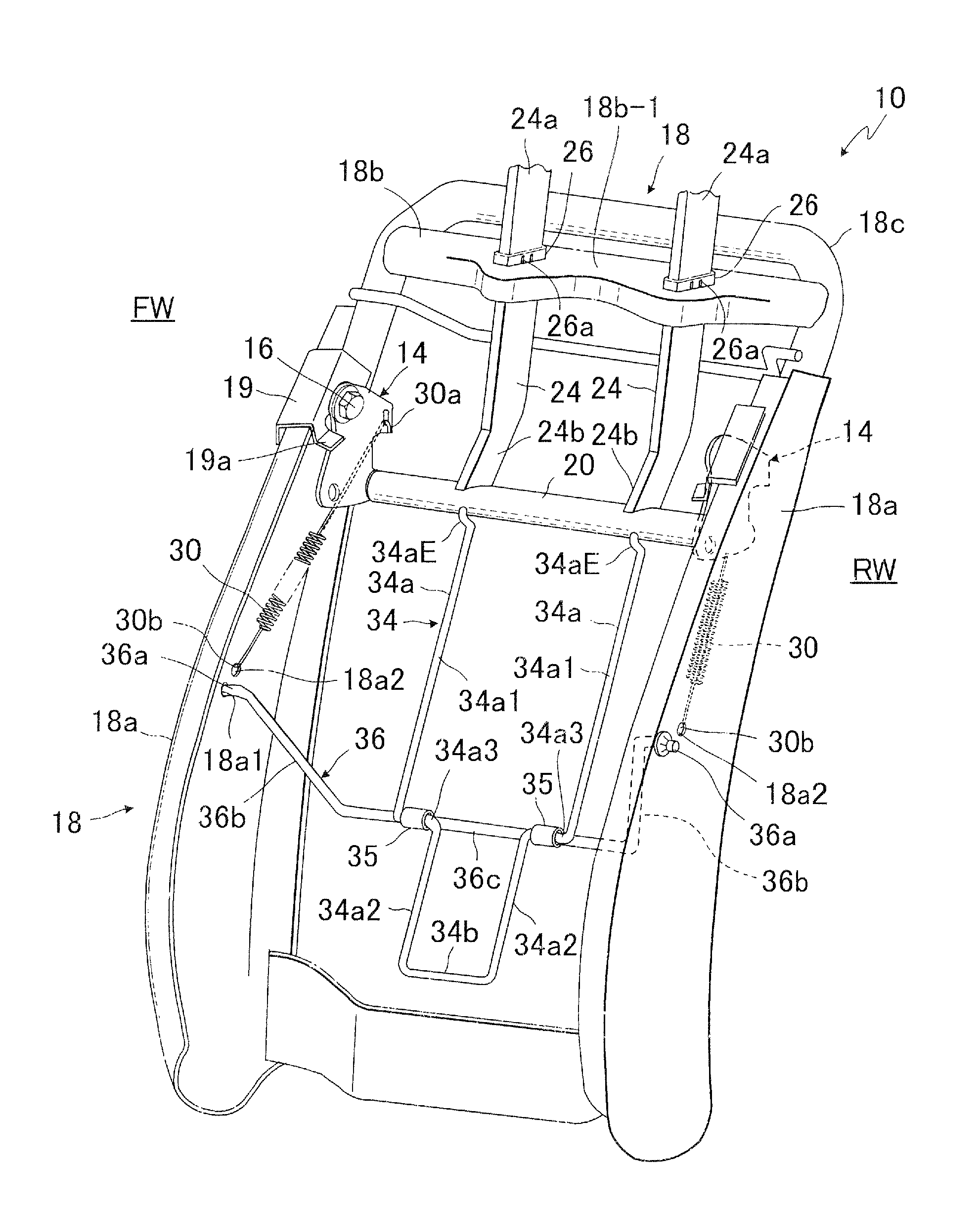
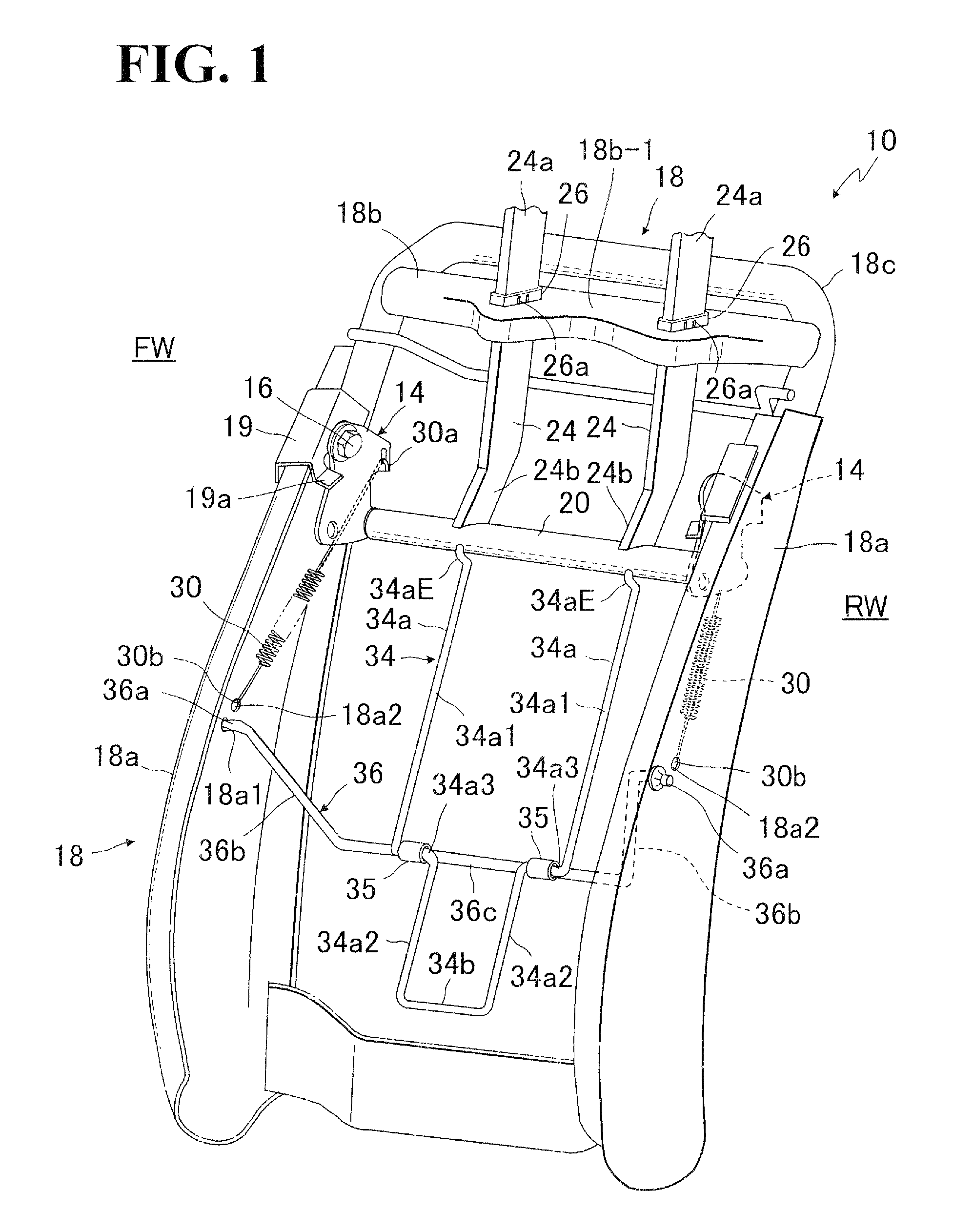
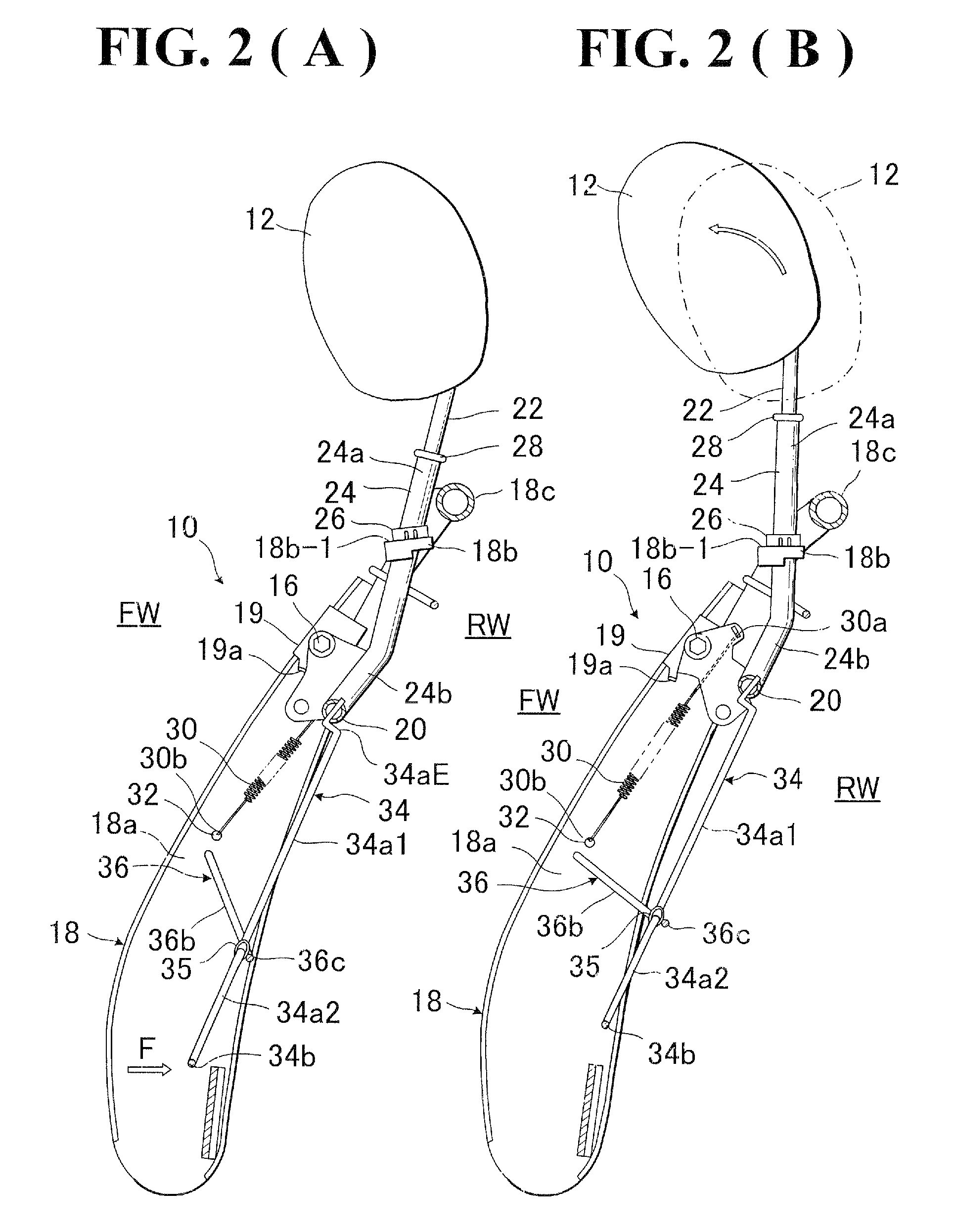
[0040]Referring to FIGS. 1 to 6(B), there are illustrated a first exemplary embodiment and a second alternative exemplary embodiment with regard to a seat back structure of vehicle seat in accordance with the preset invention. It is noted that the vehicle seat itself is not shown in the drawings, which comprises a seat back (10) to be elaborated hereinafter and an unshown seat cushion, but, it should be understood that a seat occupant (not shown) is to sit on the vehicle seat and rest his or her lumbar and dorsal parts on the seat back (10).

[0041]As shown, the seat back (10) is provided with an headrest (12) of an emergency active type workable in rear-end collision case, wherein, when a rear-end collision occurs, in response to a backward great pressure applied from a seat occupant on the vehicle seat under a backward inertia of the seat occupant the headrest (12) will be immediately displaced upwardly from a lower home point (indicated by the one-dot chained lines) to a given poin...


PUM


Abstract

In a seat back with movable headrest, a pressure receiving element is movably provided, which includes pressure receiving regions for receiving loads applied from lumber and dorsal parts of seat occupant. The pressure receiving element is movably connected with a crank member which is movably provided between two lateral frame members of seat back frame. Further, that pressure receiving element is connected with a support shaft extended between a par of rotating links rotatably arranged on the respective afore-said two lateral frame members. A biasing element is provided to normally bias the headrest to a home position.

Description

BACKGROUND OF THE INVENTION[0001]1. Field of the Invention[0002]The present invention relates to a seat back structure of vehicle seat provided with a movable headrest. In particular, the invention is directed to a seat back structure of vehicle seat of the type comprising a headrest movably provided on the seat back and a pressure receiving element provided in the seat back and operatively connected with the headrest, with the arrangement thereof being such that when a rear-end collision occurs and a backward load is applied from a seat occupant to the pressure receiving element under a backward inertia of that seat occupant, the headrest is forcibly displaced forwardly and upwardly toward a point adjacent to a head of the seat occupant.[0003]2. Description of Prior Art[0004]Disclosed and known for example from the Japanese Laid-Open Patent Publication No. 11-34708 is a seat back structure of the foregoing kind which is designed for protecting a seat occupant's head against a rear-...

Claims


Application Information

Patent Timeline
Patent Type & Authority Patents(United States)
IPC IPC(8): B60N2/42B60N2/427B60N2/48B60R21/00
CPCB60N2/4838B60N2/4885B60N2/838B60N2/888
Inventor YOKOTA, MASAAKIKOIKE, ATSUSHI
Owner TACHI S CO LTD
Why Eureka
Try Eureka