Vehicle transformer

a technology for vehicle transformers and transformers, applied in transformers/reacts, basic electric elements, electrical apparatus, etc., can solve the problems of increasing the number of parts and the insulating oil within the pipe, and the connection work takes a long time, so as to reduce the size and weight of the vehicle transformer, the pipe connection work is easier

Inactive Publication Date: 2010-07-20
MITSUBISHI ELECTRIC CORP
View PDF15 Cites 9 Cited by
  • Summary
  • Abstract
  • Description
  • Claims
  • Application Information

AI Technical Summary

Benefits of technology

[0009]According to the vehicle transformer of the invention, two of the first and second cooling medium channels are formed by partitioning the interior of the tank into two with the partition member, both of the cooling medium channels are communicated at one end side and the first cooling medium channel and one end of the cooling unit as well as the second cooling medium channel and the other end of the cooling unit are communicated at the other end side, respectively, and thereby, the cooling medium is circulated through the first cooling medium channel and the second cooling medium channel. Therefore, it is not necessary to run the connecting tube for connecting the tank and the cooling unit, the long connecting tube is no longer necessary and the pipe connection work becomes easier, and reduction in size and weight of the vehicle transformer can be realized.

Problems solved by technology

Accordingly, there are problems that a space for running the connecting tube 36 is necessary, and the number of parts and the insulating oil within the pipe are increased and the connection work takes a long time.

Method used


Image

  • Vehicle transformer
  • Vehicle transformer
  • Vehicle transformer

Examples


embodiment 1

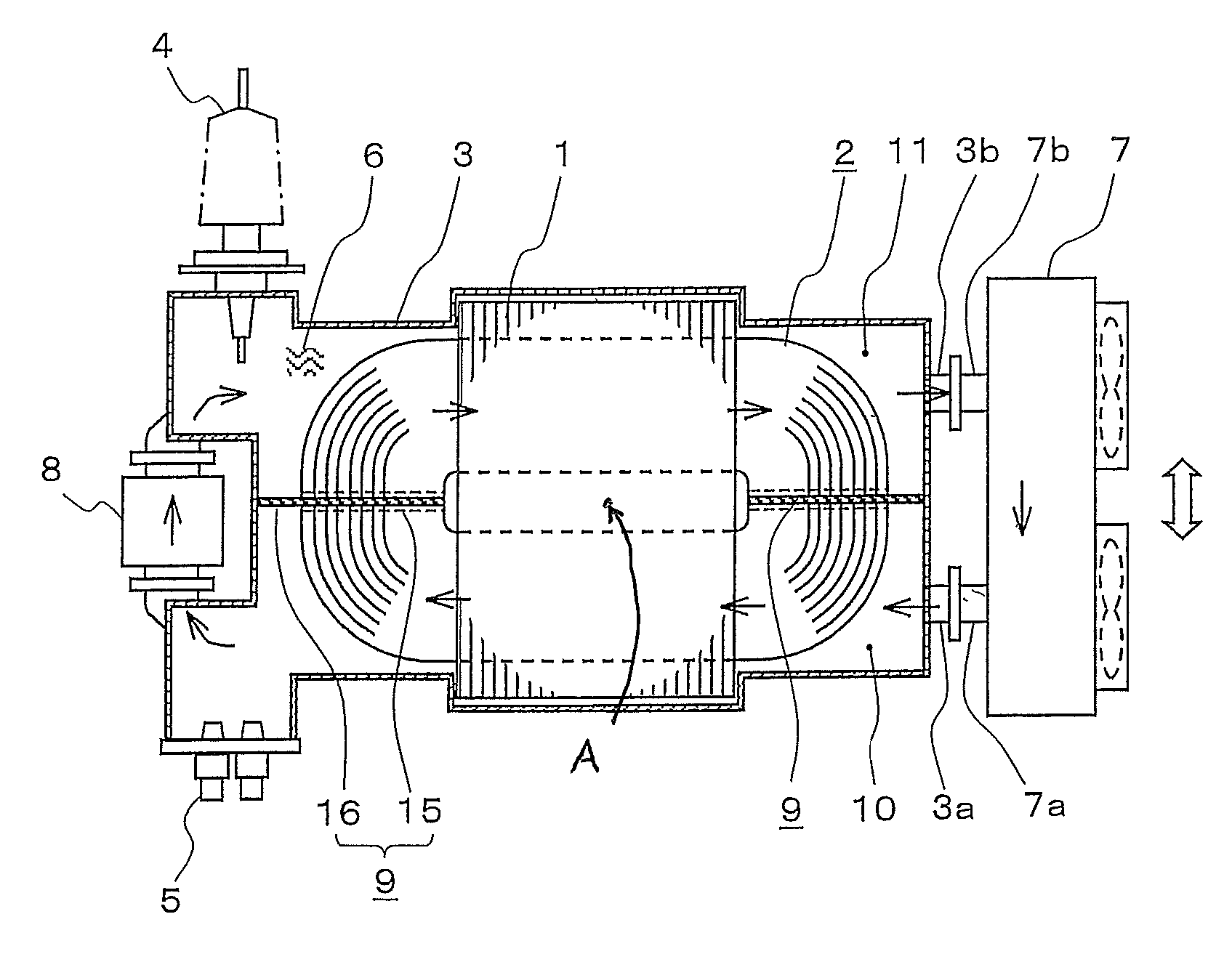
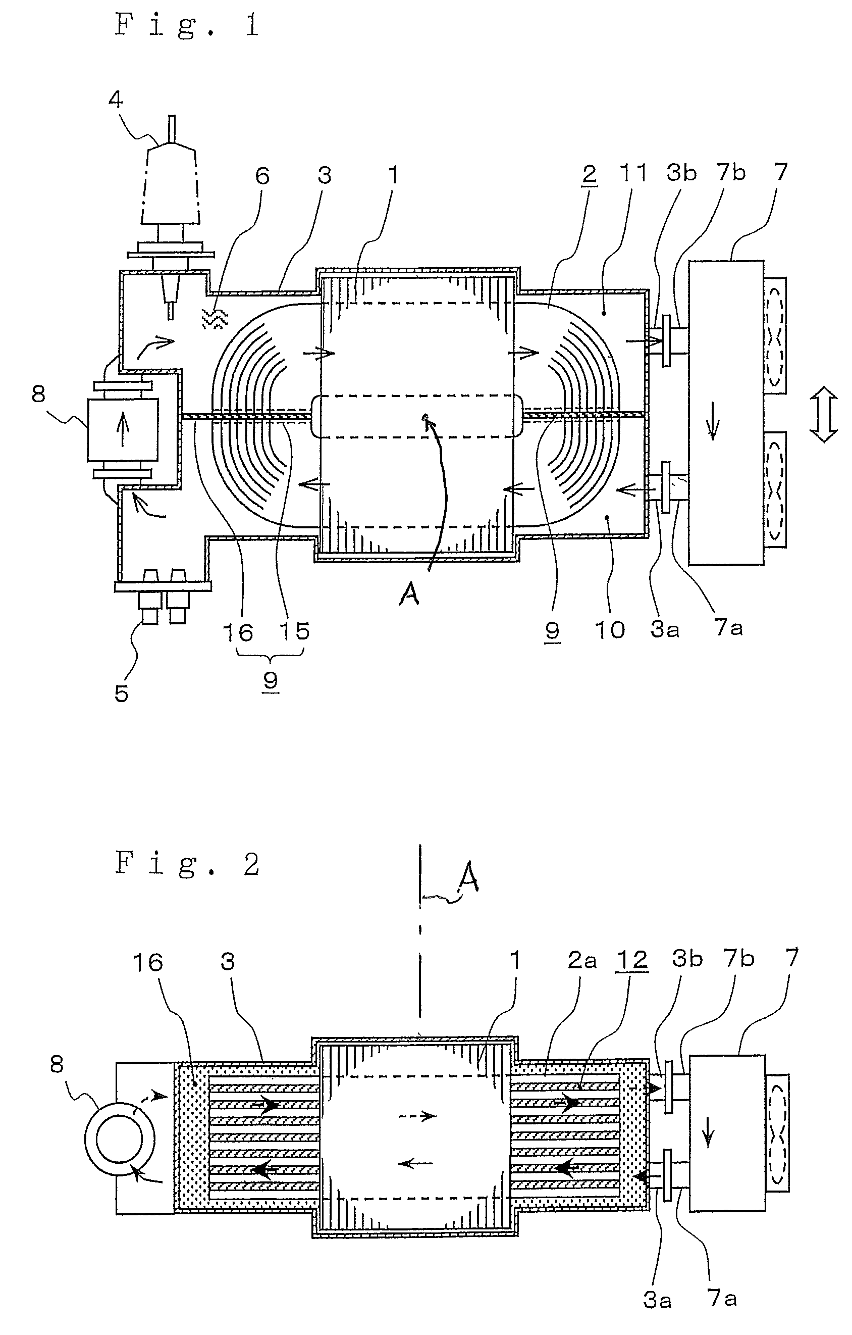
[0020]FIG. 1 is a plan sectional view showing an internal structure of a vehicle transformer according to embodiment 1, and FIG. 1 is an internal structure diagram seen from the floor of a vehicle toward the ground side and a thick arrow shows the traveling direction of the vehicle. FIG. 2 is a front sectional view showing a section of the center part seen from the side of FIG. 1. The vehicle transformer is mounted under the floor of the vehicle so that the orthogonal direction to the paper surface in the front sectional view of FIG. 2 may be the traveling direction of the vehicle. As below, the configuration will be explained according to the drawings.

[0021]A core 1 is a three-leg core with laminated thin steel plates, and a high-tension and low-tension winding 2 is wounded around its center leg. The winding 2 is configured by preparing a plurality of coil plates 2a formed by winding a rectangular wire (or circular wire) into an oval shape about an axis A in the plan view, and alte...

embodiment 2

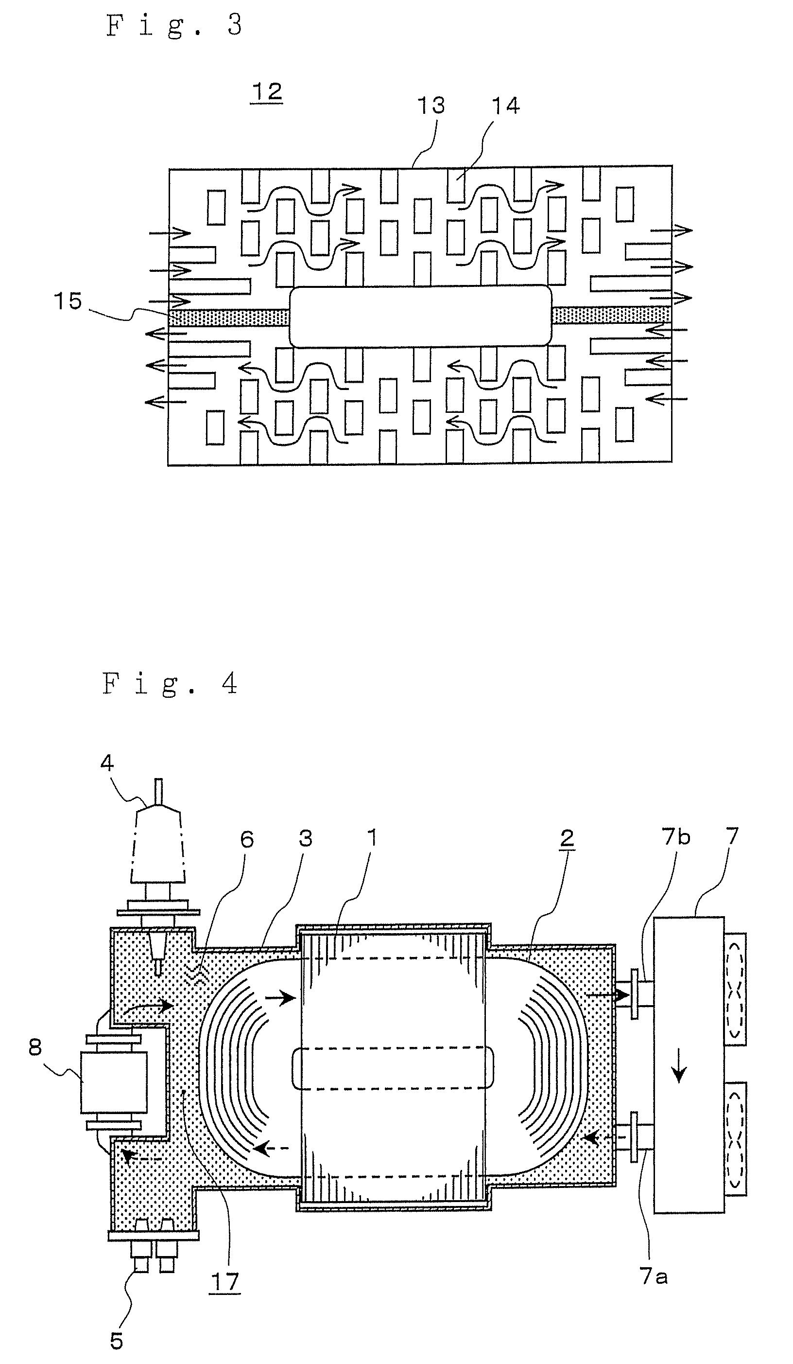
[0039]FIG. 4 is a plan sectional view showing an internal structure of a vehicle transformer according to embodiment 2, and FIG. 5 is a front sectional view showing a section of the center part of FIG. 4.

[0040]The vehicle transformer of embodiment 2 is basically equal to the vehicle transformer of embodiment 1 except that the insertion direction of the partition member is different, and the same signs are assigned to the equal parts and the description thereof will be omitted. The description will be made centering on the difference.

[0041]As shown in FIGS. 4, 5, a partition member 17 of embodiment 2 is inserted in parallel to the coil plate 2a surface of the winding 2 nearly at the center part of the winding 2 in the vertical direction to be horizontal when the vehicle transformer is mounted on a vehicle. As described using FIG. 5, the interior of the tank 3 is vertically divided into two by the partition member 17, and a first cooling medium channel 18 is formed at the lower side a...

embodiment 3

[0046]FIG. 7 is a plan sectional view showing an internal structure of a vehicle transformer according to embodiment 3,and FIG. 8 is a front sectional view showing a section of the center part of FIG. 7.

[0047]The same signs are assigned to the equal parts to those in FIG. 1 and FIG. 2 of embodiment 1 and the description thereof will be omitted, and the description will be made centering on the difference.

[0048]The difference is in that the attachment structure of the cooling unit to the tank. Further, a cooing unit 23 of embodiment 3 shows a self-cooling type. That is, cooling is performed utilizing traveling wind occurring during traveling of a vehicle (shown by a thick arrow in FIG. 7).

[0049]Embodiment 3 is characterized in that the surface of the tank 3 at the side where the inlet and outlet of the cooling medium are provided in embodiment 1 or 2 is also used as an attachment surface to which the cooling unit 23 is directly attached and an attachment flange 22 is provided. In the...


PUM

PropertyMeasurementUnit
sizeaaaaaaaaaa
weightaaaaaaaaaa
internal structureaaaaaaaaaa

Abstract

In a vehicle transformer including a core 1, a winding 2, a rectangular tank 3 holding them, a cooling unit 7 for cooling a cooling medium 6 filling the tank 3, and a circulating pump 8 for forcibly circulating the cooling medium 6, a partition member 9 is provided for dividing an interior of the tank 3 into two and the partition member 9 divides a channel of the cooling medium 6 flowing within the winding 2 into a first cooling medium channel 10 and a second cooling medium channel 11, and both of the cooling medium channels 10, 11 are communicated at one end side of the tank 3 and the cooling unit 7 connected to both of the cooling medium channels 10, 11 is provided at the other end for the cooling medium 6 to flow and circulate in the first cooling medium channel 10 and the second cooling medium channel 11. Thereby, the connection between the tank and the cooling unit is simplified and a vehicle transformer reduced in size and weight is obtained.

Description

TECHNICAL FIELD[0001]The present invention relates to a vehicle transformer mounted under a vehicle floor for use.BACKGROUND ART[0002]Generally, an insulating oil as a cooling medium also serving for insulation is sealed within a tank of a vehicle transformer, and the insulating oil is circulated with an oil feed pump and introduced into a cooling unit provided outside of the tank for cooling. FIG. 9 is a plan view showing a conventional vehicle transformer including such a cooling structure. FIG. 9 is a plan view seen from the floor of a vehicle 31 toward the ground side, and a thick arrow indicates the traveling direction of the vehicle. As shown in the drawing, a transformer main body 32 in which a core and a coil (not shown) are held and an insulating oil is sealed, and a cooling unit 33 for cooling the insulating oil are mounted under the floor of the vehicle 31. An outlet 32b of the insulating oil is provided at one end and an inlet 32a is provided at the other end of the tran...

Claims


Application Information

Patent Timeline
Patent Type & Authority Patents(United States)
IPC IPC(8): H01F27/10H01F27/02H01F27/08H01F27/06H01F27/30
CPCH01F27/12H01F27/322
Inventor KIUCHI, HIROSHIKOBA, YUTAKA
Owner MITSUBISHI ELECTRIC CORP
Why Eureka
Try Eureka