Method and device for forming steam for household appliance

a technology for household appliances and steam, applied in liquid transfer devices, lighting and heating devices, immersion heating arrangements, etc., can solve the problems of not reaching the anticipated efficiency and water cannot be vaporized immediately

Inactive Publication Date: 2010-07-20
YOU TUMING
View PDF15 Cites 25 Cited by
  • Summary
  • Abstract
  • Description
  • Claims
  • Application Information

AI Technical Summary

Benefits of technology

[0005]The present invention is to provide the device and the method for forming steam used for household appliance. The major advantage of the invention is to overcome the drawback of the existing device and method that steam comes out mixed with a lot of water droplets.
[0007]The method for forming steam, including: 1) causing water to drop into spiral tube chamber through the inner of heated spiral tube chamber; 2) causing water to collide with the side wall of the spiral tube chamber, and is vaporized, then diffuse along the spiral tube chamber; 3) allowing the part of water droplets to diffuse with steam and contact with the side wall of the spiral tube chamber to vaporize; and 4) obtaining steam at the outer end of the spiral tube chamber.
[0008]The device for forming steam used for household appliance, comprising: a spiral tube chamber, a facility for heating set on the outside of spiral tube chamber, a water intake on the inner end of the spiral tube chamber, and a steam outlet on the outer end of the spiral tube chamber.
[0009]The device for forming steam used for household appliance mentioned above, wherein the spiral tube chamber is on the heating unit, wherein the electric heating element, which is buried in the body of the heating unit, constitutes the device.
[0010]The structure of heating unit can have two designs as described below:
[0011]1) The heating unit includes the main body of the heating unit and the cover plate which is fixed on the top of the main body of the heating unit, two spiral grooves, which are respectively machined in the opposite surface of the main body of the heating unit and the cover plate, constitute the spiral groove. The electric heating element is buried in the main body of the heating unit, the water intake is formed on the upper surface of the cover plate facing to the inner end of the spiral groove, the steam outlet is formed on the upper surface of the cover plate facing to the outer end of the spiral groove.

Problems solved by technology

The method mentioned above has a drawback that water cannot be vaporized immediately, water droplets which are not vaporized are guided by formed steam, then burst with formed steam from the holes, so that the steam mixes with a lot of water droplets.
It can not reach anticipated efficiency.

Method used


Image

  • Method and device for forming steam for household appliance
  • Method and device for forming steam for household appliance
  • Method and device for forming steam for household appliance

Examples


first embodiment

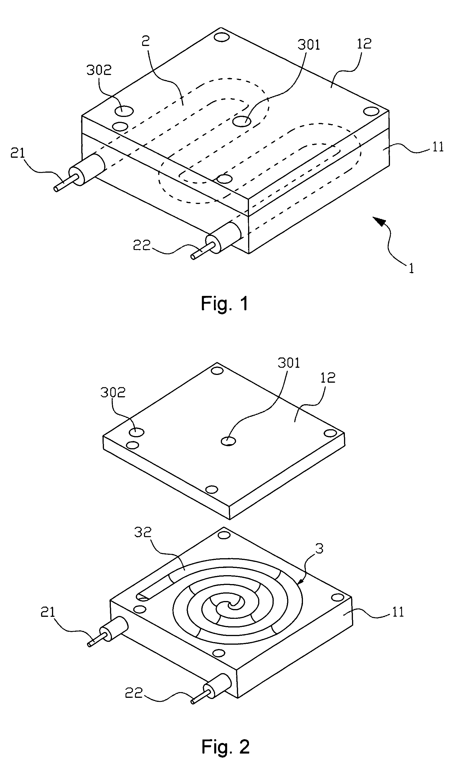
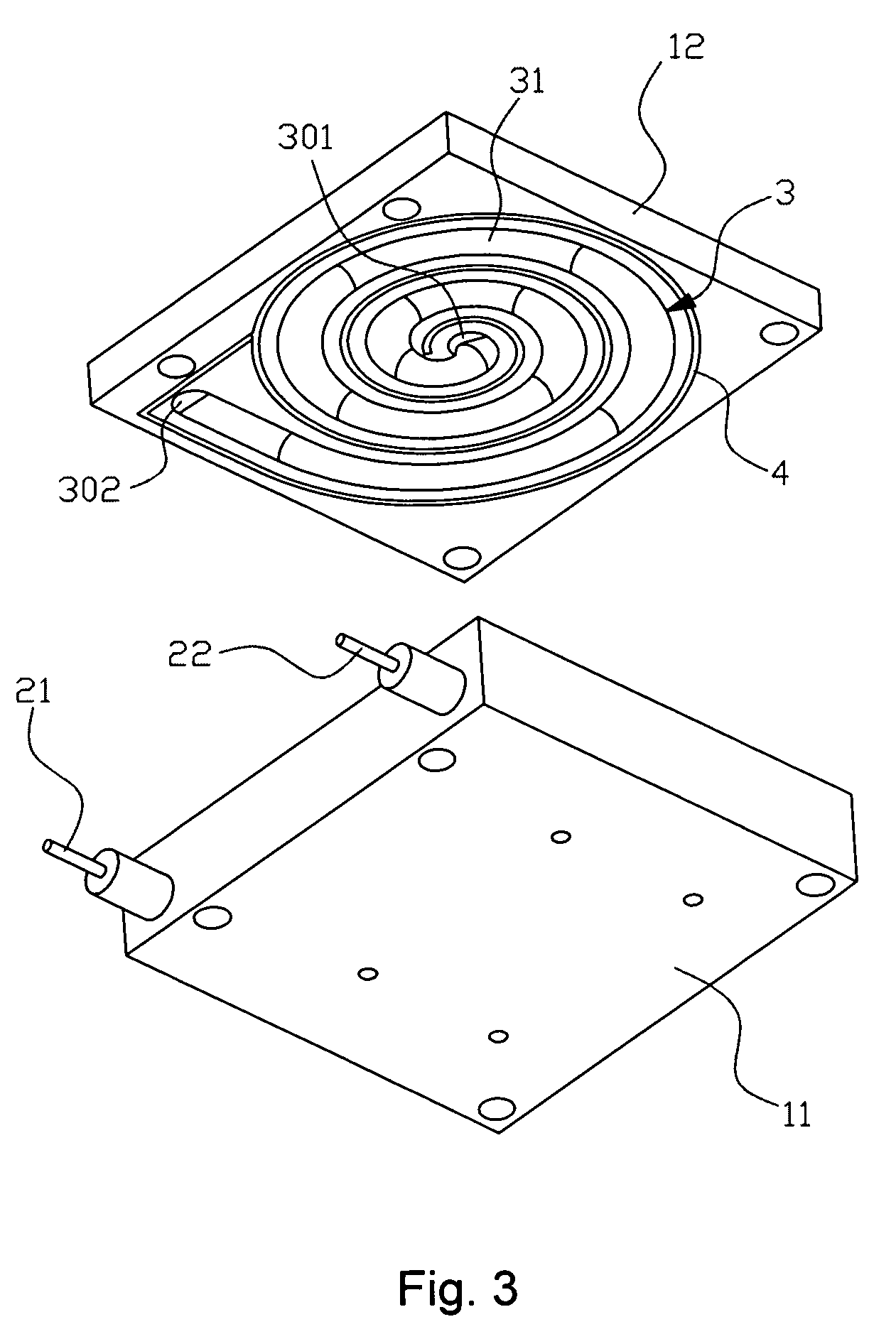
[0029]the present invention model, referring to FIG. 1, is explained as follow: the device for forming steam contains a heating unit 1, which is comprised of the main body of heating unit 11 and the cover plate 12 which is located on the top of the main body of the heating unit 11, they are fixed by screws. The electric heating element 2 is buried in the main body of heating Unit 11, and two power connectors 21, 22 connected with the end of electric heating element 2, so the electric heating element is a heating facility for the heating unit.

[0030]Referring to both FIG. 2 and FIG. 3, when the main body of heating unit 11 and the cover plate 12 are fixed with regard to each other, two spiral grooves 32, 32′ (not shown in the figures), which are respectively set on the opposite surface of the main body 11 and cover plate 12, constitute whole spiral tube chamber 3. Water can enter into the spiral tube chamber 3 through water intake 301 which is positioned on the top of cover plate 12 f...

second embodiment

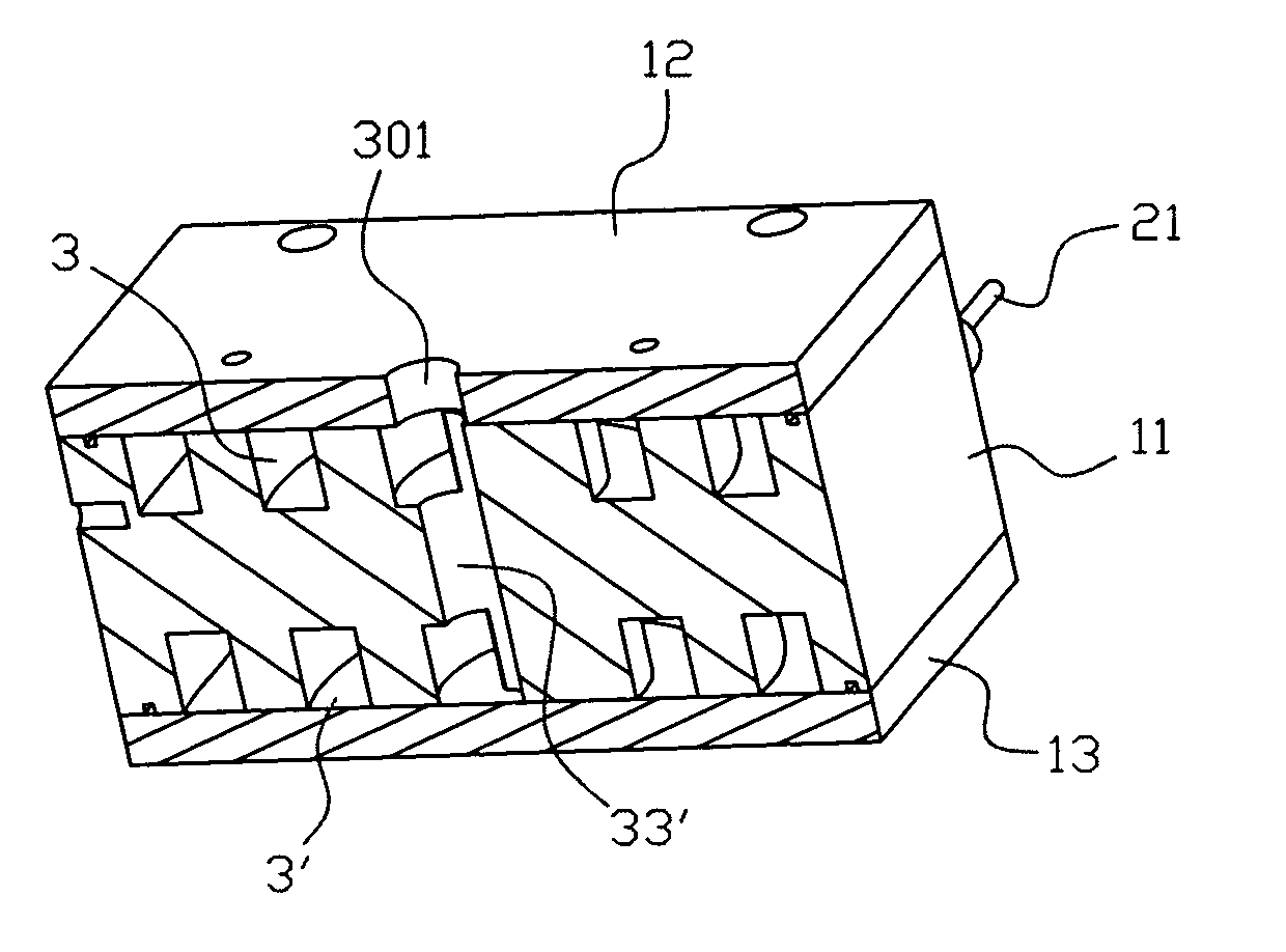
[0034]the present invention, referring to FIG. 4, comprising: the heating unit 1 that contain the main body of the heating unit 11, the upper cover plate 12 that is set on the top of the main body of the heating unit and lower cover plate 13 that is set on the bottom of the main body of the heating unit, they are fixed by screws. The electric heating element 2, which is buried in the main body of the heating unit, constitutes the facility for heating. Two power connectors. 21, 22, which are set outside of the main body of the heating unit 11, are connected with the heating element 2.

[0035]Referring to FIG. 5, the spiral groove 31, which is machined on the top of the main body of the heating unit 11, forms the first spiral tube chamber 3 enclosed with the lower surface of upper cover plate 12. Referring to FIG. 6, the spiral groove 31′, which is machined on the bottom of the main body of the heating unit 11, is turned to the second spiral tube chamber 3′ with the upper surface of the...

third embodiment

[0039]the present invention, referring to FIG. 9, is used for soleplate of iron. The heating element 2, which is buried in the inner of soleplate 11, constitutes the facility for heating soleplate 11. Two power connectors 21, 22, which are set outside of soleplate 11, are connected with the heating element 2.

[0040]Referring to FIG. 10, the spiral groove 31, which is formed on top of soleplate 11, is turned into the spiral tube chamber 3 enclosed with the cover plate 12 which is fixed on the top of spiral groove 31. The water intake 301 is formed on the cover plate 12 facing to the inner end of the spiral tube chamber 3. The vapor outlet is formed on the bottom of soleplate 11 facing to outer end of the spiral tube chamber 3.

[0041]The configuration and working principle of the present embodiment are similar to the first embodiment. The major difference is that the shape of the spiral tube chamber 3 is adjusted to fit the shape of soleplate due to the embodiment used in iron, the oute...


PUM


Abstract

The device and the method for forming steam are used for household appliance. Principle: water enters into the heated spiral tube chamber through the inner end of the spiral tube chamber; water contacts the side wall of the spiral tube chamber, and is vaporized, then diffused along the spiral tube chamber; part of the water droplets diffuses with vapor, and contacts the side wall of the spiral tube chamber gradually, then is vaporized; vapor is obtained from the outer end of the spiral tube chamber. In one word, the invention provides a method to obtain “dry” steam which doesn't contain water. It is more efficient than other facilities.

Description

CROSS-REFERENCE TO RELATED APPLICATIONS[0001]This application claims priority to Chinese Patent Application No. 200610135235.7, filed on Nov. 20, 2006, the teachings of which are incorporated hereto by reference in their entirety.FIELD OF THE INVENTION[0002]The present invention relates to the technology field of forming steam, and more particularly, to provide the method and the device for forming steam for household appliance.BACKGROUND OF THE INVENTION[0003]Some household appliances, for example, the electric iron, steam cleaner, steam vacuum, hair curling machine and microwave oven etc, usually contain a device relative to forming steam. Taking the electric iron for instance, steam given out from soleplate causes the ironed cloth to be humidified uniformly. The process is as below: Controlled by the valve, water is dropped into the forming steam chamber which is formed on the top of soleplate. When heating soleplate, water collides with the bottom of heated forming steam chamber...

Claims


Application Information

Patent Timeline
Patent Type & Authority Patents(United States)
IPC IPC(8): F24H1/10
CPCD06F39/008D06F75/10D06F75/20F22B1/282F22B27/14F22B37/12
Inventor YOU, TUMING
Owner YOU TUMING
Why Eureka
Try Eureka