Telescopic wing with articulated structural spar

a technology of articulating structure and wing, which is applied in the direction of canard-type aircraft, transportation and packaging, aircraft convertible vehicles, etc., can solve the problems of difficult movement and storage of aircraft, the wing of foldable aircraft would experience significant adverse wind loading on its wings, and the wing of foldable aircraft is not well suited to use with roadable aircraft, etc., to achieve the effect of enhancing the rigidity of the spar assembly

Active Publication Date: 2010-07-27
DHALL SANJAY
View PDF17 Cites 64 Cited by
  • Summary
  • Abstract
  • Description
  • Claims
  • Application Information

AI Technical Summary

Benefits of technology

[0010]To enhance rigidity of the spar assembly, each link may have a cross-sectional height and a cross-sectional width such that the cross-sectional height is equal to or greater than the cross-sectional width.

Problems solved by technology

Aircraft wings are necessarily large, and their size makes it difficult to move and store an aircraft when it is not in flight.
Since foldable wing designs leave the entire wing exposed when folded, a roadable aircraft having folded wings would experience significant adverse wind loading on its wings when operated as a surface vehicle.
Thus, foldable wings are not well suited to use with roadable aircraft.
Although telescopic wing designs necessarily contemplate a retracted position wherein the extent to which the wing is exposed during surface travel is reduced, a majority of previous designs offer only a limited degree of wing size reduction.
Since roadable aircraft must be designed so as to fit within the travel lane of a roadway, those telescopic wing structures that provide only limited wing size reduction and thus are not suited for use with roadable aircraft.
Although telescopic wing designs have been proposed that do provide a significant reduction in the length of the wing by using telescopic structural spars, telescoping structural members are costly to produce, and require complex extension and retraction mechanisms.

Method used


Image

  • Telescopic wing with articulated structural spar
  • Telescopic wing with articulated structural spar
  • Telescopic wing with articulated structural spar

Examples


Embodiment Construction

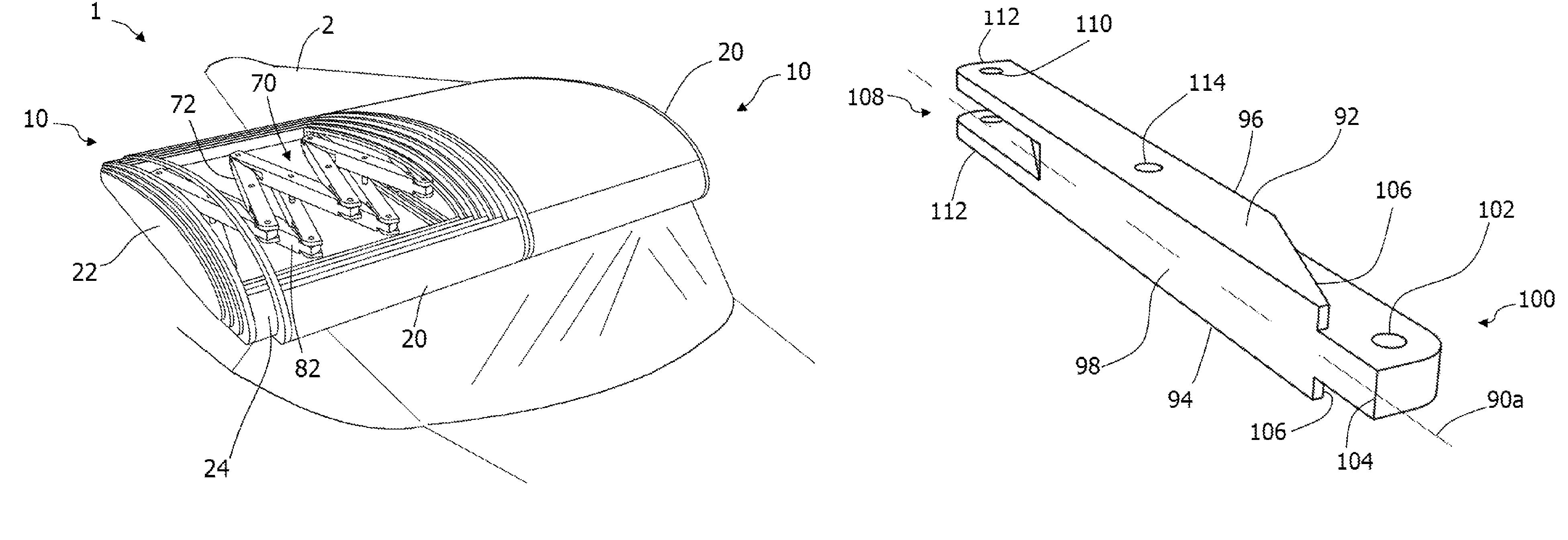
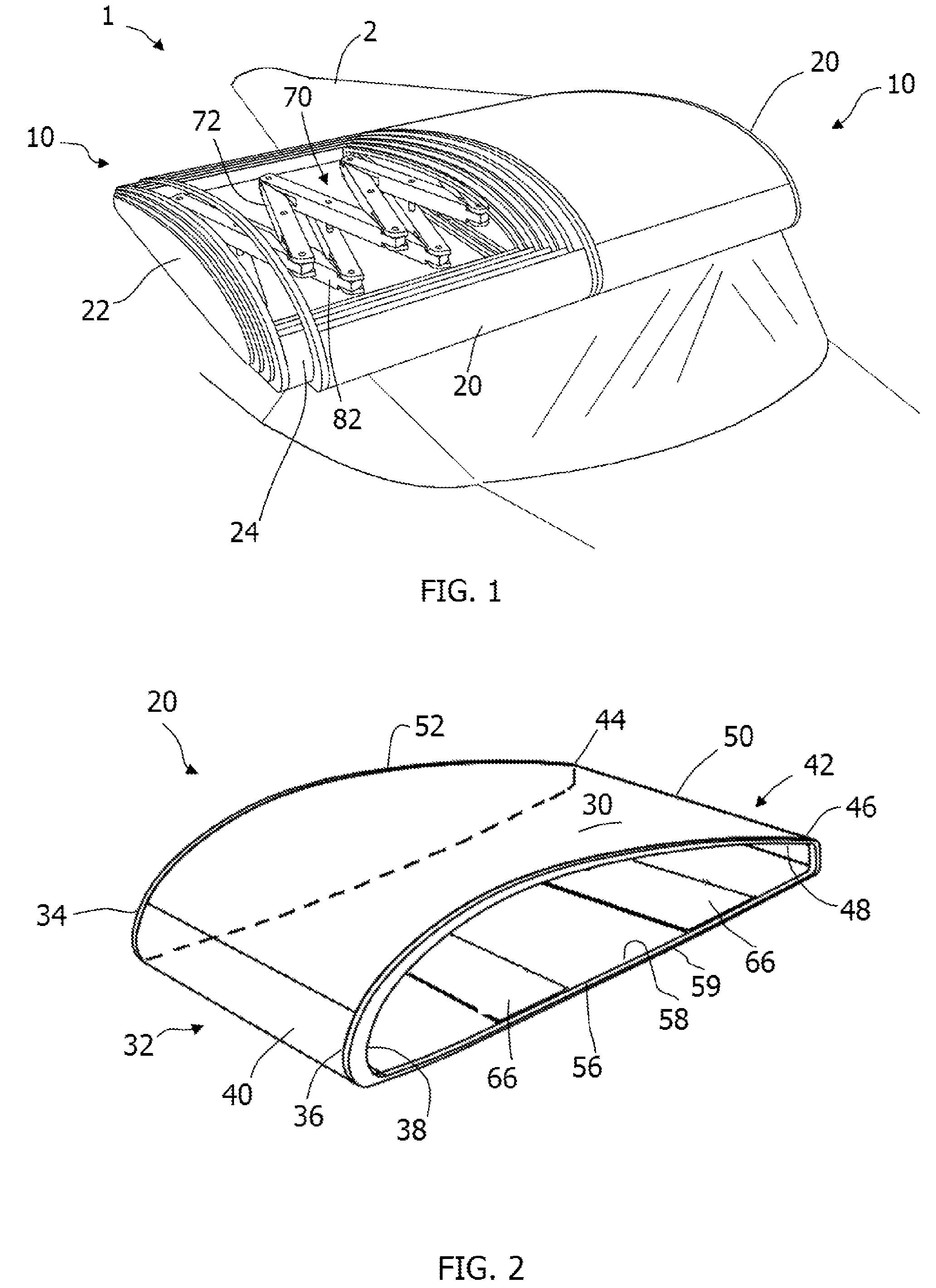
[0040]Referring to the drawings, the invention will be seen to most generally comprise a telescopic aircraft wing having an articulated structural spar that connects a tip portion of the aircraft wing to a root portion of the aircraft wing for telescopic retraction of the tip portion into the root portion.

[0041]As shown in FIG. 1, a telescopic wing 10 according to a first embodiment of the invention moves between an extended position, to allow the telescopic wing 10 may be used as a flying surface, and a retracted position, to allow for storage of the telescopic wing 10. In particular, a pair of the telescopic wings 10 may be connected to the fuselage 2 of an aircraft 1 in a side-by-side configuration for use as the primary flying surfaces of the aircraft 1. It is particularly contemplated that the telescopic wing 10 is applicable to aircraft 1 that are designed to be convertible for use either as an airplane or as a road-worthy surface vehicle. However, it should be understood that...


PUM


Abstract

A telescopic aircraft wing having an articulated structural spar. The telescopic wing includes a root portion and a tip portion that is telescopically related to the root portion. A spar assembly connects the root portion to the tip portion for providing structural support to the tip portion, and the spar assembly has a plurality of links that are pivotally connected to one another. The spar assembly moves the tip portion with respect to the root portion between an extended position and a retracted position.

Description

CROSS-REFERENCE TO RELATED APPLICATIONS[0001]This application claims the benefit of U.S. Provisional Patent Application No. 60 / 856,916, filed on Nov. 6, 2006.FIELD OF THE INVENTION[0002]The invention relates to the field of aircraft wing structures wherein the space occupied by the wings may be reduced when they are not in use.BACKGROUND OF THE INVENTION[0003]Aircraft wings are necessarily large, and their size makes it difficult to move and store an aircraft when it is not in flight. Accordingly, many designs have been previously proposed for reducing the space occupied by aircraft wings when the aircraft is not in flight. One area of particular applicability of such designs arises with regard to so-called roadable aircraft. Generally stated, roadable aircraft are aircraft that may be converted for surface travel upon a roadway.[0004]Most of the previously-proposed designs for reducing the space occupied by the wings of an aircraft when it is not in flight can be characterized eith...

Claims


Application Information

Patent Timeline
Patent Type & Authority Patents(United States)
IPC IPC(8): B64C3/56
CPCB60F5/02B64C3/56B64C37/00B64C39/12
Inventor DHALL, SANJAY
Owner DHALL SANJAY
Why Eureka
Try Eureka