
Distributed power train operation responsive to an unexpected brake pipe fluid flow condition

a technology of fluid flow and distribution power, applied in the direction of braking system, process and machine control, instruments, etc., can solve the problems of remote locomotives near the end of the train, slow brake application at rail cars, and failure to implement fail-safe modes of operation

Active Publication Date: 2010-07-27
GE GLOBAL SOURCING LLC
View PDF14 Cites 16 Cited by
  • Summary
  • Abstract
  • Description
  • Claims
  • Application Information

AI Technical Summary

Benefits of technology

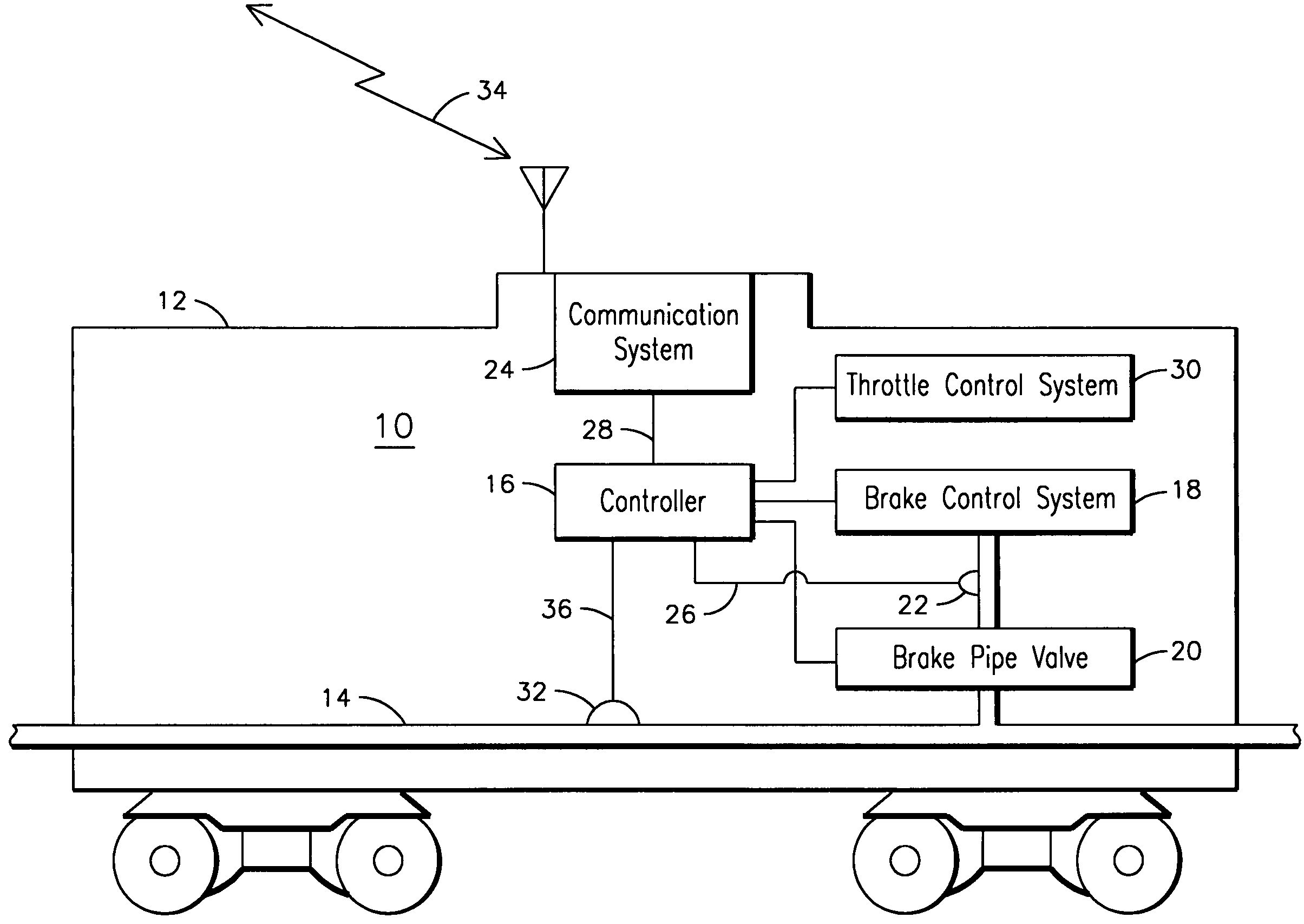
The patent is about a system that controls the operation of a remote locomotive in a distributed power train. The system uses wireless communication to transmit braking and traction commands to the remote locomotive. However, if there is a loss of communication, the system is designed to automatically compensate for the fluid flow in the brake pipe to ensure that all remote locomotives receive the same information. This helps to bring the brakes on or off quickly in case of an emergency. The system also includes a controller that receives fluid flow or pressure signals to control the brakes and a brake pipe valve to prevent interference with the fluid flow. Overall, the system ensures that the brakes are applied and released quickly and efficiently in a distributed power train.

Problems solved by technology

However, brake pipe venting at only the lead locomotive of a train requires propagation of the corresponding brake pipe pressure reduction along the length of the train, thus slowing brake application at rail cars and remote locomotives near the end of the train.
If the time period expires before communications are re-established, the remote may implement a fail safe mode of operation, such as disabling charging or venting of the brake pipe at the remote, and / or reducing a traction condition of the remote.

Method used


Image

  • Distributed power train operation responsive to an unexpected brake pipe fluid flow condition
  • Distributed power train operation responsive to an unexpected brake pipe fluid flow condition

Examples


Embodiment Construction

[0006]The present inventors have observed in a distributed power train that when an unexpected brake pipe fluid flow condition inconsistent with a last radio commanded braking operation is sensed by an upstream remote locomotive, the brake pipe flow condition may not be propagated to downstream remote locomotives. For example, a brake pipe brake fluid flow command corresponding to the lead locomotive commanding a minimum service brake application may be interpreted by a first remote locomotive sensing a pressure drop in the brake pipe as a leak. The first remote locomotive may then charge the brake pipe to correct for the leak, resulting in disruption of the minimum application pressure wave being propagated along the brake pipe to downstream remotes. Consequently, the downstream remotes may remain in a traction state and continue to charge the brake pipe despite a minimum service brake application indication being issued by the lead locomotive, leading to undesirable longer stoppin...


PUM


Abstract

A method of propagating a brake pipe braking command along a fluid carrying brake pipe (14) interconnecting members of a transportation system, the transportation system comprising a communication system (24) for exchanging information between a controlling member of the system and controlled members of the system includes identifying an unexpected brake pipe fluid flow condition at a first controlled member (e.g. 12) of the transportation system inconsistent with a communication system braking command issued by a controlling member of the transportation system. The method also includes disabling an ability of the first controlled member to control a brake pipe flow so that a brake pipe braking command issued by the controlling member is propagated along a brake pipe to a second controlled member of the transportation system downstream of the first controlled member with reduced brake pipe fluid flow interference from the first controlled member.

Description

FIELD OF THE INVENTION[0001]This invention relates generally to the field of locomotive control, and more particularly to controlling an operation of a remote locomotive in a distributed power train responsive to an unexpected brake pipe fluid flow condition.BACKGROUND OF THE INVENTION[0002]Distributed power train operation supplies motive power from a lead locomotive and one or more remote locomotives spaced apart from the lead locomotive in a train consist. Each lead and remote locomotive includes an air brake control system for controlling braking operations and a communication system for exchanging information between lead and remote locomotives over a communication link. A brake pipe fluidically interconnects each of the locomotives and rail cars of the train wherein modulation of a fluid flow, such as a fluid pressure in the brake pipe, is conventionally used to indicate desired braking operations. Brake application is typically accomplished by venting, or reducing a pressure ...

Claims


Application Information

Patent Timeline
Patent Type & Authority Patents(United States)
IPC IPC(8): B60T13/00
CPCB60T13/66B60T17/228
Inventor SMITH, EUGENE A.
Owner GE GLOBAL SOURCING LLC
Learn More