Backlight unit

a backlight unit and backlight technology, applied in the field of backlight units, can solve the problems of difficult to discharge the heat generated by the led, and achieve the effect of excellent heat discharging efficiency and slim external appearan

Inactive Publication Date: 2010-07-27
SAMSUNG ELECTRONICS CO LTD
View PDF27 Cites 46 Cited by
  • Summary
  • Abstract
  • Description
  • Claims
  • Application Information

AI Technical Summary

Benefits of technology

[0008]The present general inventive concept provides a backlight unit having a slim external appearance and an excellent heat discharging efficiency.

Problems solved by technology

In the conventional backlight unit, however, it is difficult to discharge heat generated from the LED.
If the heat is not quickly discharged, the ambient temperature is increased to cause a problem to a neighboring system.

Method used


Image

  • Backlight unit
  • Backlight unit
  • Backlight unit

Examples


Embodiment Construction

[0032]Reference will now be made in detail to the embodiments of the present general inventive concept, examples of which are illustrated in the accompanying drawings, wherein like reference numerals refer to the like elements throughout. The embodiments are described below in order to explain the present general inventive concept while referring to the figures.

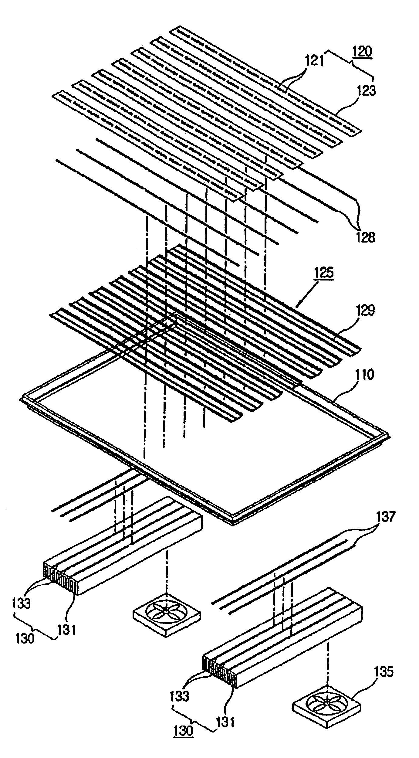
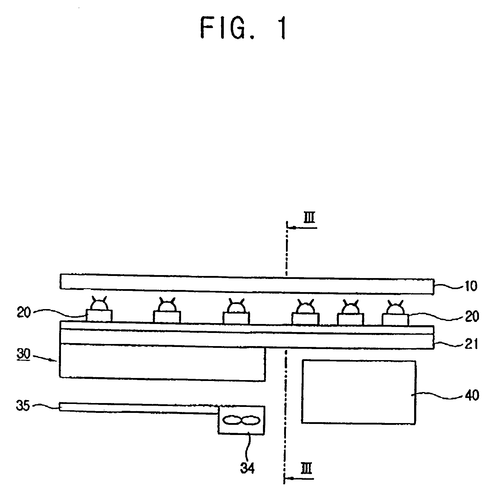
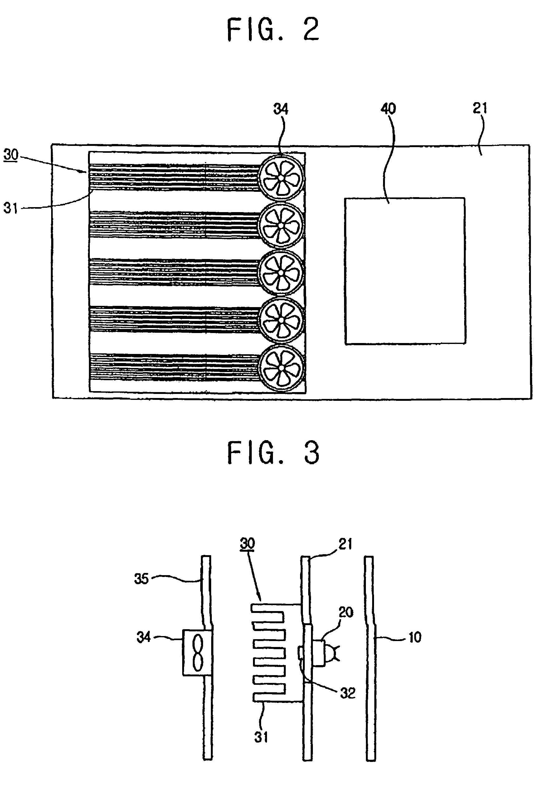
[0033]Referring to FIGS. 1 and 3, a backlight unit 1 according to an embodiment of the present general inventive concept comprises a light source provided in a rear side of a display panel 10 to illuminate light to thereby allow a picture to be displayed on the display panel 10, a support plate 21 to support the light source, a printed circuit board (PCB) 40 to drive the light source and the like, and a heat discharging device to discharge heat generated from the light source.

[0034]The light source includes but is not limited to a multiplicity of light emitting diodes (LEDs) 20 electrically connected to the PCB 40, thereby em...


PUM


Abstract

A backlight unit having light sources to illuminate light to a display panel includes a support plate to support the light sources, a printed circuit board provided on a first region of the support plate, and a heat discharging member provided on a second region of the support plate to discharge heat generated from the light sources. The backlight unit has a slim external appearance and an excellent heat discharging efficiency.

Description

CROSS-REFERENCE TO RELATED APPLICATIONS[0001]This application claims the benefit of Korean Patent Application No. 2004-93881, filed on Nov. 17, 2004, and Korean Patent Application No. 2004-79134, filed on Oct. 5, 2004, in the Korean Intellectual Property Office, the disclosure of which is incorporated herein by reference.BACKGROUND OF THE INVENTION[0002]1. Field of the Invention[0003]The present general inventive concept relates to a backlight unit, and more particularly, to a backlight unit having an improved heat discharging efficiency.[0004]2. Description of the Related Art[0005]Generally, a conventional backlight unit supplies light from a back surface of a liquid crystal display (LCD) panel. The backlight unit includes a diffusion sheet to scatter and diffuse the light, a frame arranged on edges of the diffusion sheet, an LCD driving circuit board provided on a back surface of the frame, and a light emitting diode (LED) provided on the LCD driving circuit board as a light sourc...

Claims


Application Information

Patent Timeline
Patent Type & Authority Patents(United States)
IPC IPC(8): F21V7/04
CPCG02F1/133603G02F2001/133628G02F1/133628
Inventor KIM, WON-NYUNNOH, JI-HWAN
Owner SAMSUNG ELECTRONICS CO LTD
Why Eureka
Try Eureka