Keyboard

a keyboard and keyboard technology, applied in the field of keyboards, can solve the problems of easy damage to the key structure, impaired structural strength of the key structure, and still have some drawbacks in the approach, and achieve the effect of enhancing tactile feel and reducing thickness

Active Publication Date: 2017-09-28
PRIMAX ELECTRONICS LTD
View PDF0 Cites 3 Cited by
  • Summary
  • Abstract
  • Description
  • Claims
  • Application Information

AI Technical Summary

Benefits of technology

[0009]The present invention provides a keyboard with reduced thickness and enhanced tactile feel.
[0012]From the above descriptions, the keyboard of the present invention has the function of changing the heights of the keys. For operating the keyboard, the bulge of the scissors-type connecting element is controlled to be received in the first step part of the position-limiting structure. Consequently, the keycap is at a higher height. Since the height of the keycap is not limited during the normal operation of the keyboard, the movable distance of the keycap is still large enough to provide better tactile feel. For storing the keyboard, the bulge of the scissors-type connecting element is controlled to be received in the second step part of the position-limiting structure. Consequently, the height of the keycap is reduced, and the keyboard has a slim appearance. In other words, the keyboard of the present invention is capable of effectively solving the drawbacks of the conventional technologies.

Problems solved by technology

However, these approaches still have some drawbacks.
In case that the first approach is adopted, the structural strength of the key structure is impaired, and thus the key structure is easily damaged.
In case that the second approach is adopted, the tactile feel of depressing the key structure is deteriorated.
In other words, it is difficult to reduce the thickness of the keyboard while obtaining the desired tactile feel.

Method used


Image

  • Keyboard
  • Keyboard
  • Keyboard

Examples


Embodiment Construction

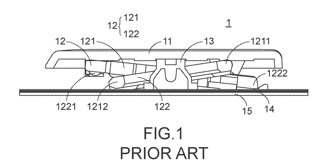
[0024]For solving the drawbacks of the conventional technologies, the present invention provides a keyboard with enhanced structural strength and slim appearance.

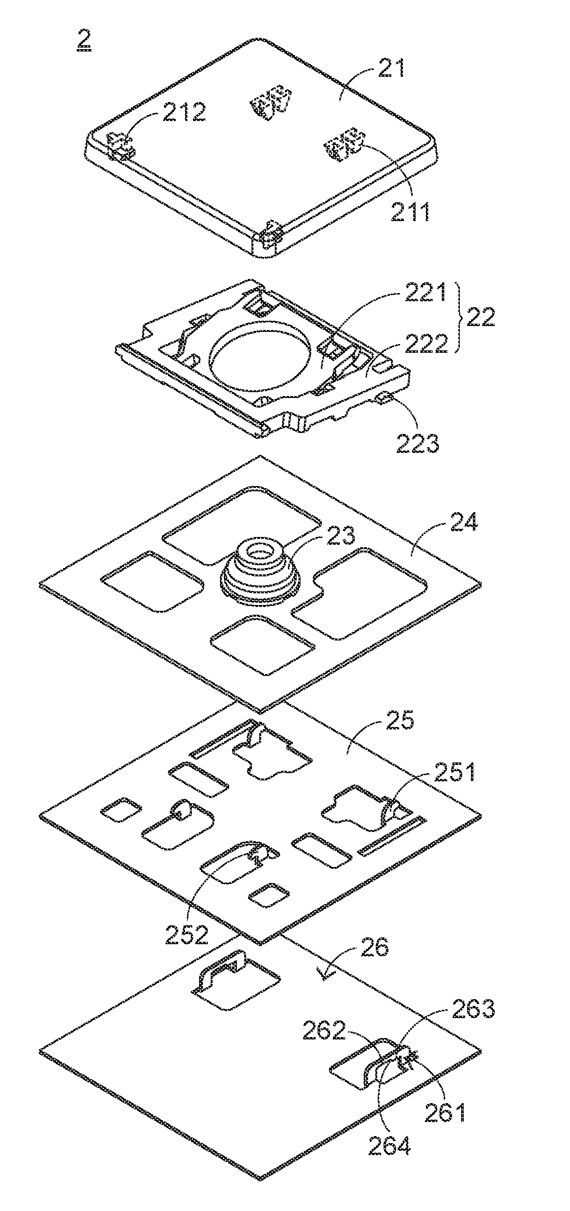
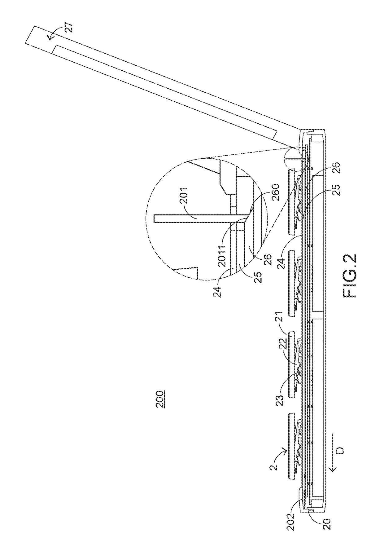
[0025]FIG. 2 is a schematic side cross-sectional view illustrating a keyboard according to a first embodiment of the present invention. FIG. 3 is a schematic exploded view illustrating a portion of the keyboard according to the first embodiment of the present invention. Please refer to FIGS. 2 and 3. The keyboard 2 is installed on a notebook computer 200. The keyboard 2 comprises a keyboard base 20, plural keycaps 21, plural scissors-type connecting elements 22, plural elastic elements 23, a membrane switch circuit member 24, a base plate 25 and a sliding plate 26. The keyboard base 20 is connected with a top cover 27. The top cover 27 is rotatable relative to the keyboard base 20 to cover the keyboard base 20. Moreover, an outer shell of the notebook computer 200 is defined by the keyboard base 20 and the top cover 27 coll...


PUM


Abstract

A keyboard includes a base plate, plural keycaps, plural scissors-type connecting elements and a sliding plate. Each scissors-type connecting element has a bulge. The gliding plate has plural position-limiting structures. The keyboard is installed on a notebook computer and connected with a top cover of the notebook computer. For operating the keyboard, the bulge is received in a first step part of the position-limiting structure. Consequently, the keycap is at a higher height. Since the keycap is at a higher height, the movable distance of the keycap is large enough to provide better tactile feel. For storing the keyboard, the bulge of the scissors-type connecting element is moved to the second step part of the position-limiting structure. Consequently, the height of the keycap is reduced, and the keyboard has a slim appearance.

Description

FIELD OF THE INVENTION[0001]The present invention relates to a keyboard, and more particularly to a slim-type keyboard.BACKGROUND OF THE INVENTION[0002]Generally, the widely-used peripheral input device of a computer system includes for example a mouse, a keyboard, a trackball, or the like. Via the keyboard, characters or symbols can be directly inputted into the computer system. As a consequence, most users and most manufacturers of input devices pay much attention to the development of keyboards. As known, a keyboard with scissors-type connecting elements is one of the widely-used keyboards.[0003]The structure of a keyboard with scissors-type connecting elements will be illustrated as follows. For succinctness, only one key structure of the keyboard is shown. FIG. 1 is a schematic side cross-sectional view illustrating a key structure of a conventional keyboard. As shown in FIG. 1, the conventional key structure 1 comprises a keycap 11, a scissors-type connecting element 12, a rub...

Claims


Application Information

Patent Timeline
Patent Type & Authority Applications(United States)
IPC IPC(8): H01H13/705H01H13/85G06F1/16H01H13/10
CPCG06F1/1662H01H13/85H01H13/10H01H13/705H01H3/125H01H2223/052H01H2231/042
Inventor WANG, YI-CHEN
Owner PRIMAX ELECTRONICS LTD
Why Eureka
Try Eureka