Supercharge Your Innovation With Domain-Expert AI Agents!

Gear drive system and method

a gear drive and gear system technology, applied in the direction of gearing, hoisting equipment, mechanical equipment, etc., can solve the problem of increasing the size of the gear system

Active Publication Date: 2010-08-03
RAYTHEON CO
View PDF8 Cites 1 Cited by
  • Summary
  • Abstract
  • Description
  • Claims
  • Application Information

AI Technical Summary

Benefits of technology

The present invention provides a low-profile gear drive system that includes a rack and pinion. The system also includes stabilizer bearings that prevent the rack and pinion from disengaging. The technical effects of this invention include a reduction in the size of the gear drive system and improved stability and reliability.

Problems solved by technology

Many conventional systems include additional structures that react to the separation force, but which also increase the size of the gear systems, which converts rotary motion to linear motion and vice versa.

Method used


Image

  • Gear drive system and method
  • Gear drive system and method
  • Gear drive system and method

Examples


Embodiment Construction

[0012]The following representative descriptions of the present invention generally relate to exemplary embodiments and the inventor's conception of the best mode, and are not intended to limit the scope, applicability or configuration of the invention in any way. Rather, the following description is intended to provide convenient illustrations for implementing various embodiments of the invention. As will become apparent, changes may be made in the function and / or arrangement of any of the elements described in the disclosed exemplary embodiments without departing from the spirit and scope of the invention.

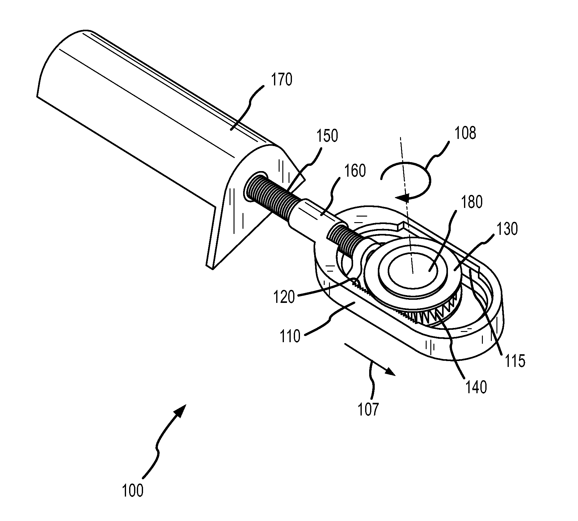
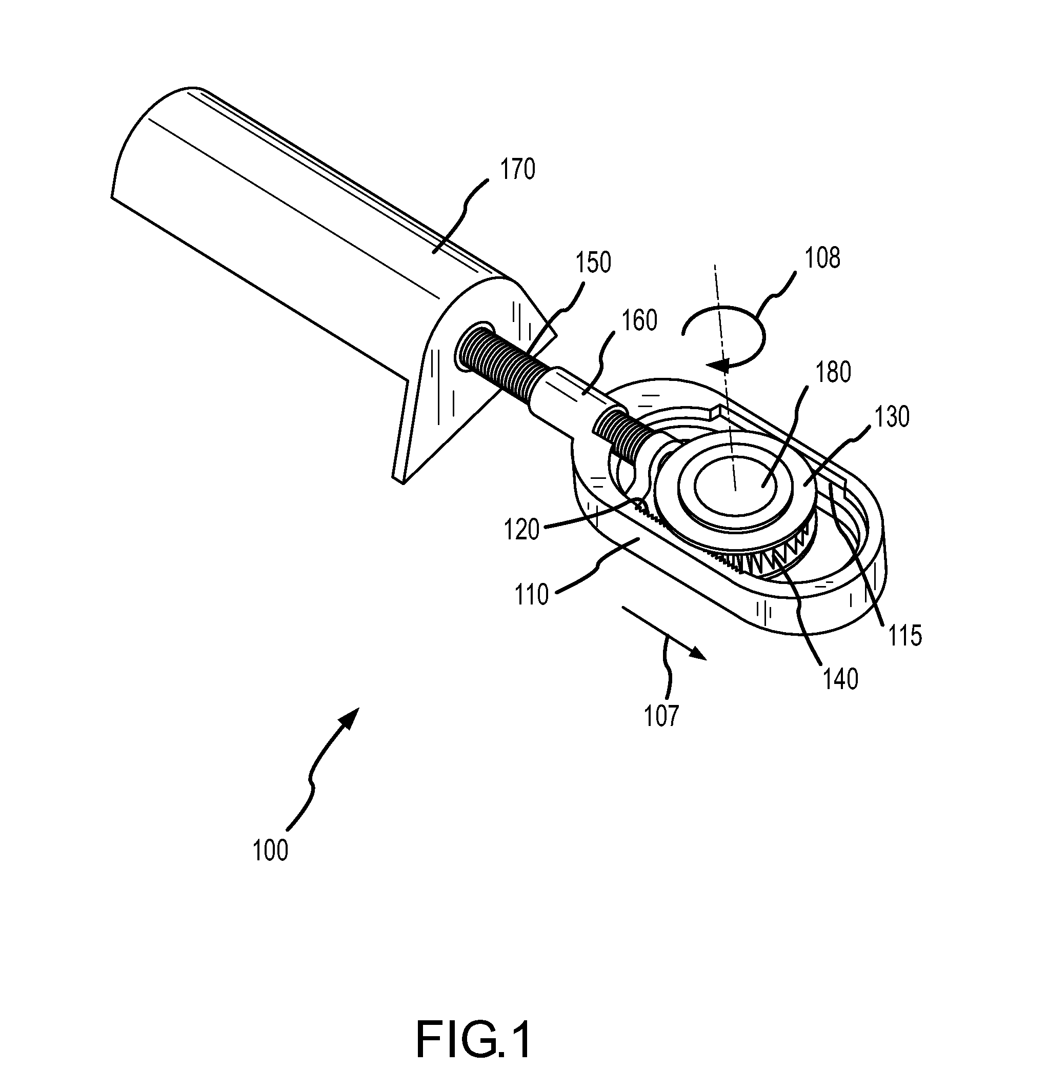
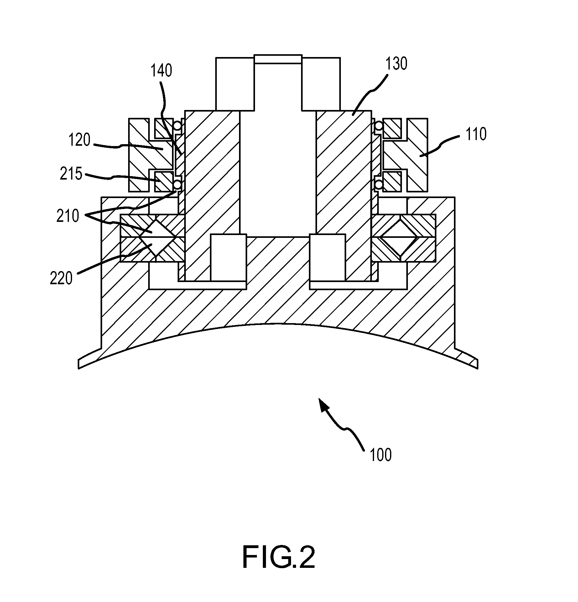
[0013]Various representative implementations of the present invention may be applied to any gear drive system. Certain representative implementations may include, for example, missile fin controls. As used herein, the terms “rack”, “pinion”, “gear” or any variation or combination thereof, are generally intended to include anything that may be characterized as elements of a gear an...


PUM


Abstract

The disclosed system, device and method for providing a low aspect rack and pinion assembly includes a rack engaged with a ball screw and a pinion. The rack is generally responsive to the rotation of the ball screw and the pinion is generally responsive to the movement of the rack. The separating forces generated by the engagement of the rack and pinion are suitably reacted by one or more stabilizer bearings engaged with the structure of the rack and pinion to prevent the rack and pinion from disengaging while maintaining a low aspect profile.

Description

GOVERNMENT LICENSE RIGHTS[0001]This invention was made with United States Government support under Contract number F08630-03-C-0047 awarded by the Department of the Air Force. The United States Government has certain rights in this invention.FIELD OF INVENTION[0002]The present invention generally concerns gear drive systems; and more particularly, representative and exemplary embodiments of the present invention generally relate to systems, devices and methods relating to low-profile rack and pinion gear arrangements.BACKGROUND OF INVENTION[0003]Gear drives are used in a wide variety of applications to perform a number of different functions. In some applications, for example, gear drives may be used to change rotational direction and alter rotational speed in a mechanical system. One common application of a gear drive system is a rack and pinion gear system, which converts rotation to linear motion. However, in order for the rack and pinion gears to remain engaged with each other, ...

Claims


Application Information

Patent Timeline
Patent Type & Authority Patents(United States)
IPC IPC(8): F16H19/04
CPCF16H19/04F42B10/64Y10T74/19744Y10T74/18096Y10T74/19819Y10T74/1967
Inventor FJERSTAD, ERIK A.
Owner RAYTHEON CO
Features
  • R&D
  • Intellectual Property
  • Life Sciences
  • Materials
  • Tech Scout
  • Unparalleled Data Quality
  • Higher Quality Content
  • 60% Fewer Hallucinations
Learn More