Transflective liquid crystal display with partially shifted reflectivity curve

a liquid crystal display and reflectivity curve technology, applied in non-linear optics, instruments, optics, etc., can solve the problems of significant discrepancy in the color and contrast of the displayed image, and achieve the effect of reducing the potential of the reflective electrode and improving the viewing quality of the transflective-type liquid crystal display

Active Publication Date: 2010-08-03
OPTRONIC SCI LLC
View PDF23 Cites 11 Cited by
  • Summary
  • Abstract
  • Description
  • Claims
  • Application Information

AI Technical Summary

Benefits of technology

[0007]The present invention provides a method and a pixel structure to improve the viewing quality of a transflective-type liquid crystal display. The pixel structure of a pixel in the liquid crystal display comprises a plurality of sub-pixel segments. Each of the sub-pixel segments comprises a transmission area and a reflection area. In the sub-pixel segments, a data line, a first gate line, a second gate line and a common line are used to control the operational voltage on the liquid crystal layer areas associated with the sub-segments. The transmission area has a transmissive electrode associated with a first charge storage capacity and the reflection area has a reflective electrode associated with a second storage capacity. The first and second gate lines can be separately set at a first control state and a second control state. The ratio of the first charge storage capacitor to the second charge storage capacity can be adjusted by an adjustment storage capacitor and controlled according to the states of the gate lines. By adjusting and controlling the adjustment storage capacitor, the potential on the reflective electrode is reduced so as to shift the reflectivity curve toward the higher voltage end. With such a charge refreshing approach, the transmissivity and reflectivity of a single-gap LCD can reach their optimal values at about the same applied voltage. However, the shifting of the reflectivity curve causes a major discrepancy between the transmissivity and reflectivity in the low brightness region and this discrepancy significantly affects the color and contrast of displayed image.
[0008]In order to improve the viewing quality of the display in the low brightness region, the transmissive electrode is connected to a further reflective electrode so as to retain part of the unshifted reflectivity curve.

Problems solved by technology

However, the shifting of the reflectivity curve causes a major discrepancy between the transmissivity and reflectivity in the low brightness region and this discrepancy significantly affects the color and contrast of displayed image.

Method used


Image

  • Transflective liquid crystal display with partially shifted reflectivity curve
  • Transflective liquid crystal display with partially shifted reflectivity curve
  • Transflective liquid crystal display with partially shifted reflectivity curve

Examples


Embodiment Construction

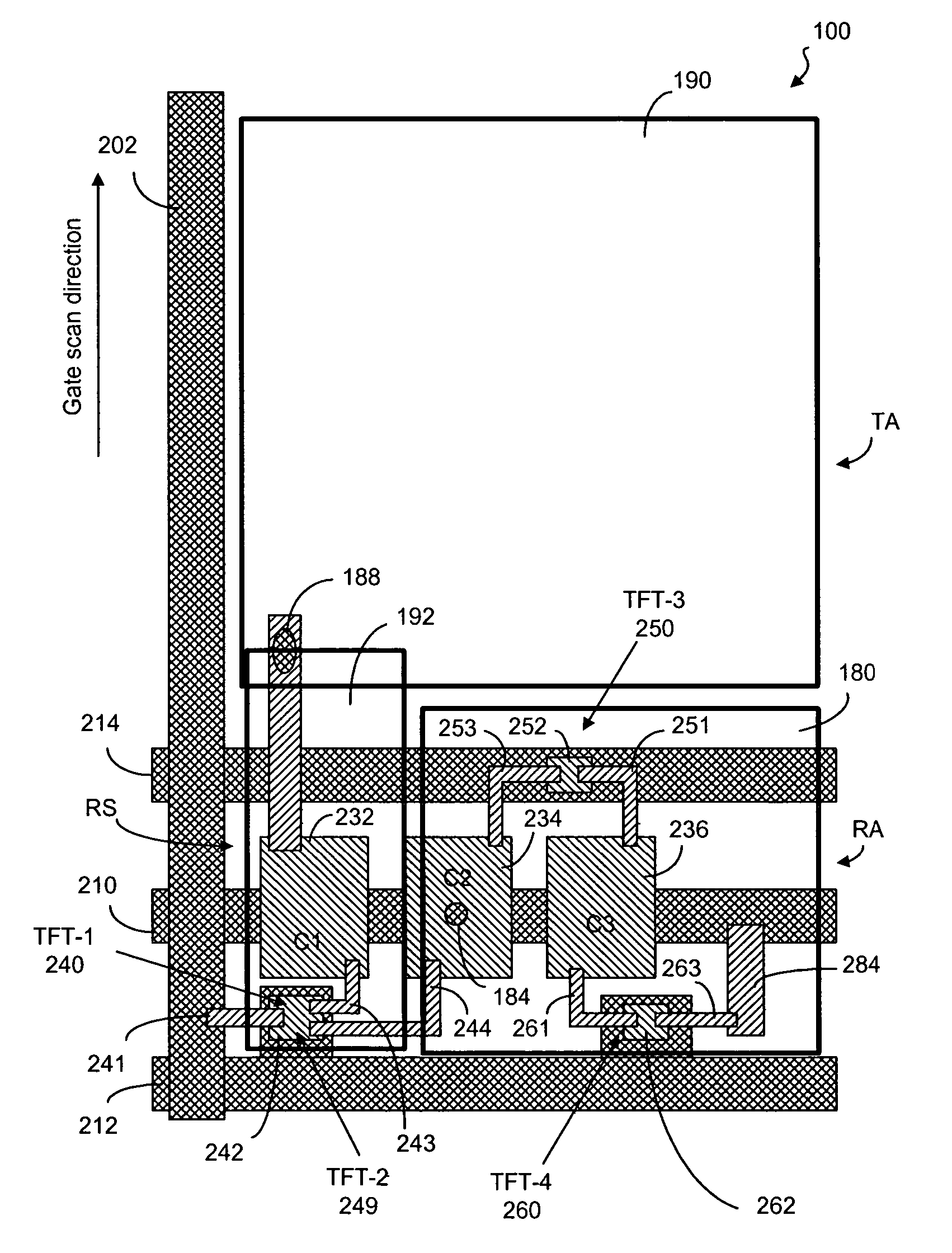
[0041]A sub-pixel segment, according to one embodiment of the present invention, is shown in FIG. 4. The sub-pixel 100 has a transmission area (TA) and a reflection area (RA). The reflection area (RA) has a reflector or reflective electrode 180. The transmission area (TA) in the sub-pixel 100 has a transparent electrode 190, electrically connected to a secondary reflector 192 in a secondary reflection section (RS). As can be seen in FIG. 5a, the sub-pixel has a color filter 152 to filter the light beam encountering the liquid crystal layer in the transmission area and also in the secondary reflection section. The reflection area has a non-color filter 150. The non-color filter 150 can be made of a clear optical material or a neutral-color filter or a very light color filter.

[0042]Alternatively, the color filter 152 only covers the transmission area, as shown in FIG. 5b. The secondary reflection section does not have a color filter or only has a non-color filter 153. The reflection a...


PUM

PropertyMeasurementUnit
reflectivityaaaaaaaaaa
optical behavioraaaaaaaaaa

Abstract

A transflective liquid crystal display having a plurality of pixels, each pixel having a plurality of color sub-pixels. Each sub-pixel comprises a reflective electrode, a transmissive electrode connected to a secondary reflective electrode. The transmissive electrode is associated with a color filter, while one only of the reflective electrode and the secondary reflective electrode is associated with a color filter. The transmissive electrode is associated with a first charge storage capacitance. The reflective electrode is associated with a second charge storage capacitance which is adjustable depending on the operating states of the liquid crystal display.

Description

CROSS REFERENCE TO RELATED APPLICATIONS[0001]The present application is related to U.S. patent application Ser. No. 11 / 146,568, filed Jun. 7, 2005, assigned to the assignee of the present invention.FIELD OF THE INVENTION[0002]The present invention relates generally to a liquid crystal display panel and, more particularly, to a transflective-type liquid crystal display panel.BACKGROUND OF THE INVENTION[0003]Due to the characteristics of thin profile and low power consumption, liquid crystal displays (LCDs) are widely used in electronic products, such as portable personal computers, digital cameras, projectors, and the like. Generally, LCD panels are classified into transmissive, reflective, and transflective types. A transmissive LCD panel uses a back-light module as its light source. A reflective LCD panel uses ambient light as its light source. A transflective LCD panel makes use of both the back-light source and ambient light.[0004]As known in the art, a color LCD panel 1 has a tw...

Claims


Application Information

Patent Timeline
Patent Type & Authority Patents(United States)
IPC IPC(8): G02F1/1343G02F1/1333
CPCG02F1/133555G02F1/13624G02F1/133514G02F2001/134345G02F1/134345
Inventor LIN, CHING-HUANCHANG, CHIH-MING
Owner OPTRONIC SCI LLC
Why Eureka
Try Eureka