Transflective liquid crystal display with gamma harmonization

a liquid crystal display and gamma harmonization technology, applied in static indicating devices, instruments, non-linear optics, etc., can solve the problems of reducing the view reducing the viewing quality of the transflective liquid crystal display, and difficult to achieve in practi

Active Publication Date: 2007-11-15
AU OPTRONICS CORP
View PDF22 Cites 9 Cited by
  • Summary
  • Abstract
  • Description
  • Claims
  • Application Information

AI Technical Summary

Benefits of technology

[0011] The present invention provides a method and a pixel structure to improve the viewing quality of a transflective-type liquid crystal display. The pixel structure of a pixel in the liquid crystal display comprises a plurality of sub-pixel segments, each of which comprises a transmission area and a reflection area. In the sub-pixel segment, a data line, a gate line, a common line connected to a common electrode, and a switching element operatively connected to the data line and the gate line are used to control the operational voltage on the liquid crystal layer areas associated with the sub-segment. The transmission area has a transmissive electrode and the reflection area has a reflective electrode. The transmissive electrode is connected to the switching element to control the liquid crystal layer in the transmission area. The reflective electrode is connected to the switching element via a separate capacitor to control the liquid crystal layer in the reflection area. The separate capacitor is used to shift the reflectance in the reflection area toward a higher voltage end in order to avoid the reflectance inversion problem. In addition, an adjustment capacitor is connected between the reflective electrode and a different common line. The adjustment capacitor is used to reduce or eliminate the discrepancy between the gamma curve associated with the transmittance and the gamma curve associated with the reflectance.

Problems solved by technology

In a single-gap transflective LCD, one of the major disadvantages is that the transmissivity of the transmission area (transmittance, the V-T curve) and the reflectivity in the reflection area (reflectance, the V-R curve) do not reach their peak values in the same voltage range.
While the double-gap design is effective in principle, it is difficult to achieve in practice mainly due to the complexity in the fabrication process.
Such discrepancy in the gamma curves degrades the view quality of a transflective LCD panel.

Method used


Image

  • Transflective liquid crystal display with gamma harmonization
  • Transflective liquid crystal display with gamma harmonization
  • Transflective liquid crystal display with gamma harmonization

Examples


Embodiment Construction

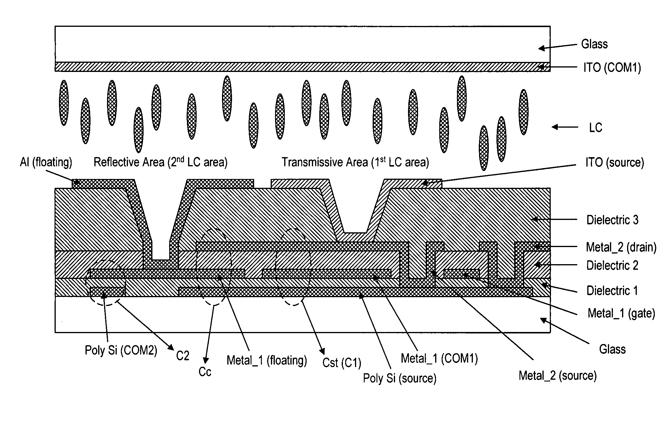
[0032] A sub-pixel segment, according to one embodiment of the present invention, is illustrated in the equivalent circuit of FIG. 8. As with a sub-pixel segment in a prior art transflective LCD display, the sub-pixel segment (m, n), according to the present invention, has a transmission area and a reflection area jointly controlled by the nth gate line and the mth data line via a switching element. The sub-pixel segment has a common electrode connected to a common line COM1. The optical behavior of the liquid crystal layer in the reflection area is controlled by the reflective electrode and the common electrode. A storage capacitor C1 is used to retain the electrical charge in the sub-pixel segment after a signal pulse in the gate line has passed.

[0033] In FIG. 8, CLC1 is the capacitance mainly attributable to the liquid crystal layer between the transmissive electrode and the common electrode, and CLC2 is the capacitance mainly attributable to the liquid crystal layer between the...


PUM

PropertyMeasurementUnit
optical transmissivityaaaaaaaaaa
transmittanceaaaaaaaaaa
reflectanceaaaaaaaaaa

Abstract

In a transflective liquid crystal display having a transmission area and the reflection area, the transmissive electrode is connected to a switching element to control the liquid crystal layer in the transmission area, and the reflective electrode is connected to the switching element via a separate capacitor to control the liquid crystal layer in the reflection area. The separate capacitor is used to shift the reflectance in the reflection area toward a higher voltage end in order to avoid the reflectance inversion problem. In addition, an adjustment capacitor is connected between the reflective electrode and a different common line. The adjustment capacitor is used to reduce or eliminate the discrepancy between the gamma curve associated with the transmittance and the gamma curve associated with the reflectance.

Description

FIELD OF THE INVENTION [0001] The present invention relates generally to a liquid crystal display panel and, more particularly, to a transflective-type liquid crystal display panel. BACKGROUND OF THE INVENTION [0002] Due to the characteristics of thin profile and low power consumption, liquid crystal displays (LCDs) are widely used in electronic products, such as portable personal computers, digital cameras, projectors, and the like. Generally, LCD panels are classified into transmissive, reflective, and transflective types. A transmissive LCD panel uses a back-light module as its light source. A reflective LCD panel uses ambient light as its light source. A transflective LCD panel makes use of both the back-light source and ambient light. [0003] As known in the art, a color LCD panel 1 has a two-dimensional array of pixels 10, as shown in FIG. 1. Each of the pixels comprises a plurality of sub-pixels, usually in three primary colors of red (R), green (G) and blue (B). These RGB col...

Claims


Application Information

Patent Timeline
Patent Type & Authority Applications(United States)
IPC IPC(8): G02F1/1335
CPCG09G3/3648G09G2320/0276G09G2300/0876G09G2300/0456
Inventor LIN, CHING-HUANSU, JENN-JIACHANG, CHIH-MING
Owner AU OPTRONICS CORP
Why Eureka
Try Eureka