Non-linear fuel transfers for gas turbines

a gas turbine and fuel transfer technology, applied in the ignition of the turbine/propulsion engine, engine starters, instruments, etc., can solve the problems of gas turbines with multiple problems, increased wear, and incorrect fuel split scheduling, so as to reduce hardware damage and wear, prolong the life of the equipment, and increase reliability

Inactive Publication Date: 2010-08-10
GENERAL ELECTRIC CO
View PDF11 Cites 26 Cited by
  • Summary
  • Abstract
  • Description
  • Claims
  • Application Information

AI Technical Summary

Benefits of technology

[0027]The present invention relates to a method by which transfers between offgoing and oncoming sources of fuel for a gas turbine may be controlled to minimize the time spent in adverse operational conditions that may cause damage to gas turbine equipment.
[0030]In accordance with a further aspect of the present invention, a method is provided for performing a transfer from an offgoing fuel type to an oncoming fuel type in a gas turbine. The method includes initially decreasing fuel flowrate from an offgoing fuel type and increasing fuel flowrate from an oncoming fuel type at a fast fuel transfer rate when adverse combustion conditions exist for the combustion system of the oncoming fuel type are avoided and simultaneously when total fuel demand for the oncoming fuel type doe not exceed a fast fuel transfer limit. Then the method includes decreasing fuel flowrate from the offgoing fuel type and increasing fuel flowrate from the oncoming fuel type at a slow fuel transfer rate for the offgoing fuel type when at least one of adverse combustion conditions exist for the combustion system of the offgoing fuel type due to low flowrate no longer exist and total fuel demand for the oncoming exceeds a fast fuel transfer limit. Further, the method includes decreasing fuel flowrate from the offgoing fuel type and increasing flow from the oncoming fuel type at the fast fuel transfer rate when adverse combustion conditions exist for the combustion system of the oncoming fuel type due to low flow and simultaneously when total fuel demand for the oncoming fuel type does not exceed a fast fuel transfer limit.

Problems solved by technology

Several problems may arise in a gas turbine during low fuel flows.
When on gas fuel and operating at low fuel flows, inaccuracies in gas control valve(s) allow for the potential of incorrect fuel split scheduling.
This incorrect gas fuel split can cause high combustion dynamics, which leads to potential combustion hardware damage and increased wear.
This is a source of combustion dynamics leading to potential damage and gas fuel nozzle wear.
Similar equipment wear and potential damage is possible on the liquid fuel nozzle at low liquid fuel flows.
Due to elevation differences between the cartridges and head effects of the liquid fuel within the can, the highest cartridge will lose liquid fuel flow first.
There is no mechanism to evenly divide the flow to all nozzles at different elevations.
These highest cartridges then experience increased wear and potential damage between the period of time when liquid fuel stops flowing through them, and liquid fuel purge is initiated.
Purge flow cannot be turned on until liquid fuel has stopped flowing as there is a significant risk of introducing liquid fuel into the purge system.
Both high combustion dynamics due to inaccurate gas fuel splits / low pressure ratio across the fuel nozzles and the potential for damage / increased wear due to low liquid fuel flows prior to purge initiation are problems corrected by the present inventive method.
This gas fuel flow error results because the gas control valve is not typically calibrated below 10% stroke, as the turbine is not intended to run with valves in these low stroke conditions for any length of time.
The inaccuracy at low gas control valve strokes will cause incorrect fuel splits to be sent into the combustor and lead to high dynamics within the combustion system.
High dynamics are known to increase combustion system wear and decrease part life.
At low liquid fuel flows field-testing has shown there is not enough head pressure to provide sufficient liquid flow to all liquid fuel nozzle cartridges.
Increased fuel nozzle wear and potential damage occurs while on low liquid fuel flow prior to initiation of purge airflow.
Liquid fuel prefill is not included in the fuel demand calculation to avoid a detrimental dip in load if the liquid fuel prefill does not reach the combustors as expected, thus creating an under-fueled condition.
The side effects of the uncontrolled fuel reaching the combustors is to supply additional energy resulting in an initial load and temperature spike and then causing global fuel demand to be driven down over time to hold the same load output.
However, high prefill rates may also affect the initial load and temperature spikes described above.
Therefore, it may not be possible to implement higher prefill flow rates without incurring penalties in the form or undesirable or unacceptable load and temperature transients.
Accordingly, there is a need to conduct fuel transfers in a manner, which increases reliability and decreases the potential for hardware damage and wear, thereby prolonging life of the equipment.
Also, there is a need to perform the modified transfers without the need for hardware changes and the associated cost and time for such modifications.

Method used


Image

  • Non-linear fuel transfers for gas turbines
  • Non-linear fuel transfers for gas turbines
  • Non-linear fuel transfers for gas turbines

Examples


Embodiment Construction

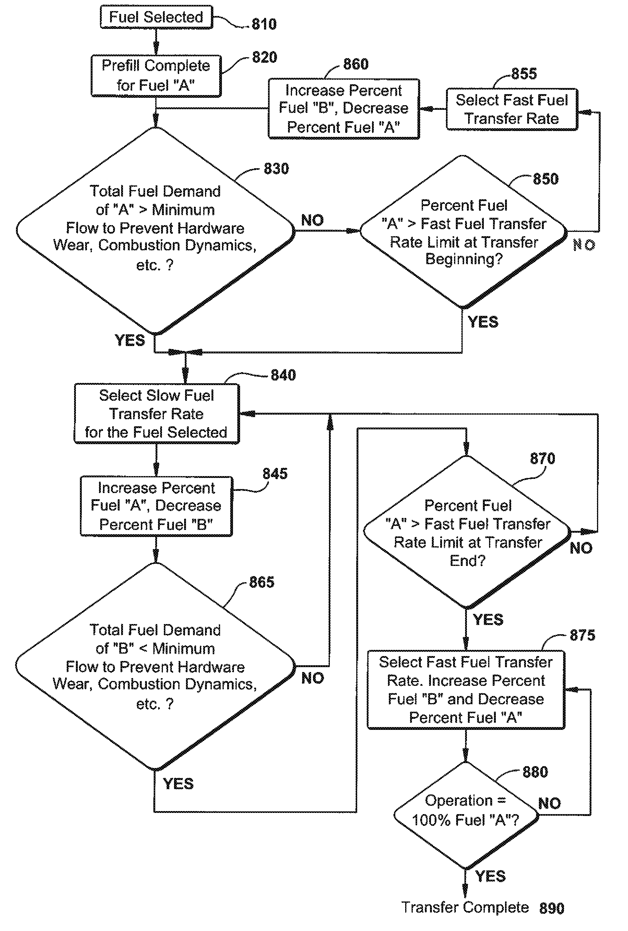
[0043]The following embodiments of the present invention have many advantages, including providing methods for transfers from liquid fuel to gas fuel and vice versa so the exposure of combustors and nozzles to adverse operational conditions resulting from low liquid fuel flow and low gas fuel flow are minimized.

[0044]Both of the problems described above result from hardware limitations, and the need is to be able to quickly get through the low flow conditions of fuel at both the beginning and end of the transfer. Moving quickly through these operational areas eliminates the increased wear or potential damage with minimum side effects on the rest of the system and overall turbine operation.

[0045]According to one aspect of the present invention, the rate of transfer between fuels is no longer a linear function but instead a multiple segment curve that is used to quickly get through problem areas of a fuel transfer. Aspects of the invention address problem areas of the transfer that ca...


PUM


Abstract

A method for controlling the rate of transfer between operation with gas and liquid fuel types to minimize the time in undesirable operational mode, thereby preventing excessive wear and damage to gas turbine hardware. The method includes completing a fuel prefill for the oncoming fuel type through the fuel system and determining if a total fuel demand for the oncoming fuel type is greater than a predetermined flow rate for the oncoming fuel type. The method also includes selecting a fuel transfer rate and transferring from the offgoing fuel type to the oncoming fuel type at the selected fuel transfer rate. Further, the method includes determining if the offgoing fuel flowrate has decreased below a predetermined flow rate for the offgoing fuel type, selecting a final fuel transfer rate and completing the transfer from offgoing fuel type to oncoming fuel type at a selected final fuel transfer rate.

Description

BACKGROUND OF THE INVENTION[0001]The invention relates generally to a method for gas turbine control and more specifically to a method for controlling the rate of transfer between operation with gas and liquid fuel types to minimize the time in undesirable operational modes, thereby preventing excessive wear and damage to gas turbine combustion hardware.[0002]Industrial gas turbines are often capable of alternatively running on liquid and gaseous fuels, e.g., natural gas. These gas turbines have fuel supply systems for both liquid and gas fuels. The gas turbines generally do not burn both gas and liquid fuels at the same time. Rather, when the gas turbine burns liquid fuel, the gas fuel supply is turned off. Similarly, when the gas turbine burns gaseous fuel, the liquid fuel supply is turned off. Fuel transfers occur during the operation of the gas turbine as the fuel supply is switched from liquid fuel to gaseous fuel, and vice versa.[0003]Gas turbines that burn both liquid and gas...

Claims


Application Information

Patent Timeline
Patent Type & Authority Patents(United States)
IPC IPC(8): F02C7/22F02C7/26
CPCF02C7/22F02C9/40F05D2270/44
Inventor IASILLO, ROBERT J.FULLER, JASON D.BACKMAN, STEVE W.ERNST-FORTIN, SAMUEL
Owner GENERAL ELECTRIC CO
Why Eureka
Try Eureka