Tilt-and-telescope steering apparatus

a technology of tilt-and-telescope and steering apparatus, which is applied in the direction of lighting apparatus, transportation and packaging, lighting apparatus, etc., can solve the problems that the conventional tilt-and-telescope steering apparatus cannot be employed in a car having a specification, cannot allow the driver to freely control the load of the telescope, etc., and achieves the effect of reducing an additional space and improving a space use efficiency

Inactive Publication Date: 2010-08-10
HL MANDO CORP
View PDF27 Cites 18 Cited by
  • Summary
  • Abstract
  • Description
  • Claims
  • Application Information

AI Technical Summary

Benefits of technology

[0016]Accordingly, the present invention has been made to solve the above-mentioned problems occurring in the prior art, and the present invention provides a tilt-and-telescope steering apparatus including an outer block between a distance block and a plate block, which are assembled together by a fastening means, which is in line with a longitudinal axis of an outer tube and is operated in cooperation with a control lever, so that the apparatus can be employed in a car having a specification requiring an adjustment bolt extending through the outer tube and can improve a space use efficiency by reducing an additional space for the adjustment bolt. Also, the present invention provides a tilt-and-telescope steering apparatus including, in substitution for a conventional bush disposed between an outer tube and an inner tube, an inner block that can move along a telescopic adjustment hole formed on the lateral surface of the outer tube while pressing the outer surface of the inner tube through the operation of the control lever, so that a driver can freely control the load of the telescope.

Problems solved by technology

Therefore, the conventional tilt-and-telescope steering apparatus can not be employed in a car having a specification, which requires an adjustment bolt extending through the outer tube and requires an additional space to be occupied by the adjustment bolt.
Moreover, the plastic material-made bushing for adjusting the frictional force between the outer tube and the inner tube in the conventional tilt-and-telescope steering apparatus cannot provide an appropriate frictional force and cannot allow a driver to freely control the load of the telescope when the bushing is worn away.

Method used


Image

  • Tilt-and-telescope steering apparatus
  • Tilt-and-telescope steering apparatus
  • Tilt-and-telescope steering apparatus

Examples


Embodiment Construction

[0023]Hereinafter, an exemplary embodiment of the present invention will be described with reference to the accompanying drawings. In the following description and drawings of the present invention, the same reference numerals are used to designate the same or similar components, and the detailed description of known functions and configurations incorporated herein is omitted to avoid making the subject matter of the present invention unclear.

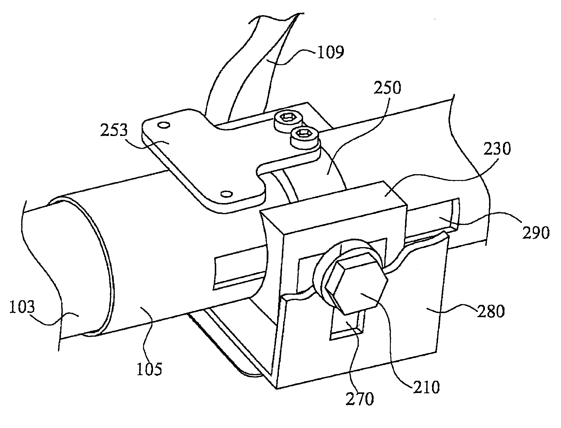
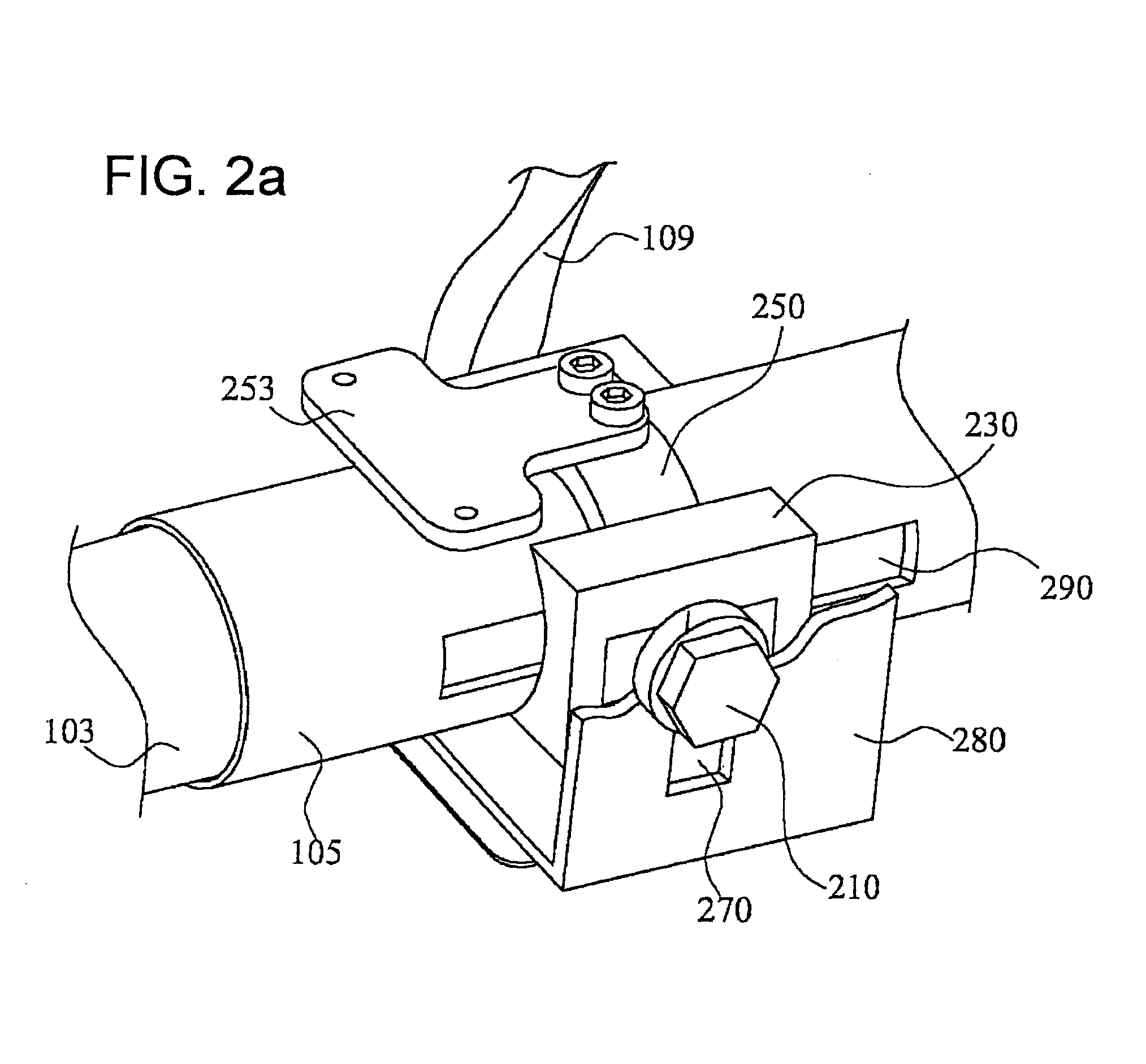
[0024]FIG. 2A is an enlarged perspective view illustrating a tilt-and-telescope steering apparatus according to an exemplary embodiment of the present invention. FIG. 2B is a section view illustrating a tilt-and-telescope steering apparatus according to an exemplary embodiment of the present invention. FIG. 2C is a partial perspective view illustrating a tilt-and-telescope steering apparatus according to an exemplary embodiment of the present invention. As illustrated in FIGS. 2A to 2C, a tilt-and-telescope steering apparatus according to the p...


PUM


Abstract

A tilt-and-telescope steering apparatus includes a plate bracket, an outer tube, a distance bracket, an outer block, and a fastening arrangement. The plate bracket surrounds an outer surface of an outer tube and has tilt adjustment holes formed on both sides of the plate bracket. The outer tube surrounds an inner tube and has telescopic adjustment hole formed in at least one side thereof. The distance bracket surrounds the outer surface of the outer tube and has fastening holes formed through both sides of the distance bracket. The outer block is positioned between the plate bracket and the distance bracket, and fastens the distance bracket according to the operation of a control lever. A fastener couples the plate bracket, the outer block, and the distance bracket to each other.

Description

CROSS-REFERENCE TO RELATED APPLICATION[0001]This non-provisional application claims priority under 35 U.S.C §119(a) on Patent Application No. 10-2007-0009946 filed in Korea on Jan. 31, 2007, the entire contents of which are hereby incorporated by reference.BACKGROUND OF THE INVENTION[0002]1. Field of the Invention[0003]The present invention relates to a tilt-and-telescope steering apparatus, and more particularly to a tilt-and-telescope steering apparatus including an outer block between a distance block and a plate block, which are assembled together by a fastening means, which is in line with a longitudinal axis of an outer tube and is operated in cooperation with a control lever, so that the apparatus can be employed in a car having a specification requiring an adjustment bolt extending through the outer tube and can improve a space use efficiency by reducing an additional space for the adjustment bolt.[0004]The present invention also relates to a tilt-and-telescope steering appa...

Claims


Application Information

Patent Timeline
Patent Type & Authority Patents(United States)
IPC IPC(8): B62D1/18
CPCB62D1/184F21V29/74F21V29/89F21S13/12
Inventor KIM, HYUNSHIN, WOO-SEOBOH, JAE-MOON
Owner HL MANDO CORP
Why Eureka
Try Eureka