Fixing system for a leading edge to the structure of an aircraft lift plane

a technology of fixing system and lift plane, which is applied in the direction of threaded fasteners, screw heads, airflow influencers, etc., can solve the problems of difficult assembly, complex structure, and heavy weigh

Active Publication Date: 2010-08-10
AIRBUS OPERATIONS SL
View PDF5 Cites 11 Cited by
  • Summary
  • Abstract
  • Description
  • Claims
  • Application Information

AI Technical Summary

Benefits of technology

[0014]The advantage of the present invention compared to the solutions existing in the state of the art is that, in a way that is easy and with simple assembly, this fixing system provides complete sealing in the interior chamber of the covering, achieving a perfect functioning of the leading edge and causing the aerodynamic flow exterior to that leading edge to be laminar. Moreover, this system facilitates the modularity and adaptation of leading edges to different configurations and sizes of lift plane, facilitating the fitting and removal of that leading edge.
[0015]Furthermore, by means of this fixing system the roughness inherent to the attachment of the leading edge to the lift plane structure of the aircraft is reduced to the minimum, with which the aerodynamic properties are notably improved.
[0016]In a particular embodiment of the invention, the fixing system includes in addition a support piece which is fixed via its lower part to the core of the forward spar of the torsion box of the lift plane by means of some first fixing means, and via its upper part to the central element of the main attachment element.
[0017]The first fixing means used for fixing the support piece to the central element of the main attachment element and to the forward spar of the torsion box of the lift plane can be fixed or detachable, the latter presenting the advantage of greater ease of fitting and detachment of the leading edge to and from the lift plane structure.
[0018]With this additional support piece certain advantages are obtained concerning greater safety and greater stability in the fixing, together with additional support for the fixing of the leading edge, and a better transmission of loads from the leading edge to the lift plane structure.
[0019]In one embodiment of the fixing means of the first arm of the main attachment element with the first lamina of the covering and the means of attachment of the second arm of the main attachment element with the second lamina of the covering, these means are welding means.

Problems solved by technology

These systems have the disadvantage of difficulty of assembly owing to the machining they need and the high tolerance, together with the need to use a larger number of additional elements which make the structure more complex and heavier.

Method used


Image

  • Fixing system for a leading edge to the structure of an aircraft lift plane
  • Fixing system for a leading edge to the structure of an aircraft lift plane
  • Fixing system for a leading edge to the structure of an aircraft lift plane

Examples


Embodiment Construction

[0010]The aim of the present invention is to overcome the drawbacks of the state of the art described above by means of a fixing system for a leading edge to the structure of an aircraft lift plane.

[0011]Said fixing system succeeds in fixing the leading edge to the structure of a lift plane in a way that is simple, thereby permitting a simple and potentially automatic fitting, thus achieving an aerodynamic flow exterior to said leading edge that is laminar, thereby improving the aerodynamic properties of the surface without the need for additional elements such as machined metallic struts or triangular wedges or spacers seen above in some of the solutions in the state of the art.

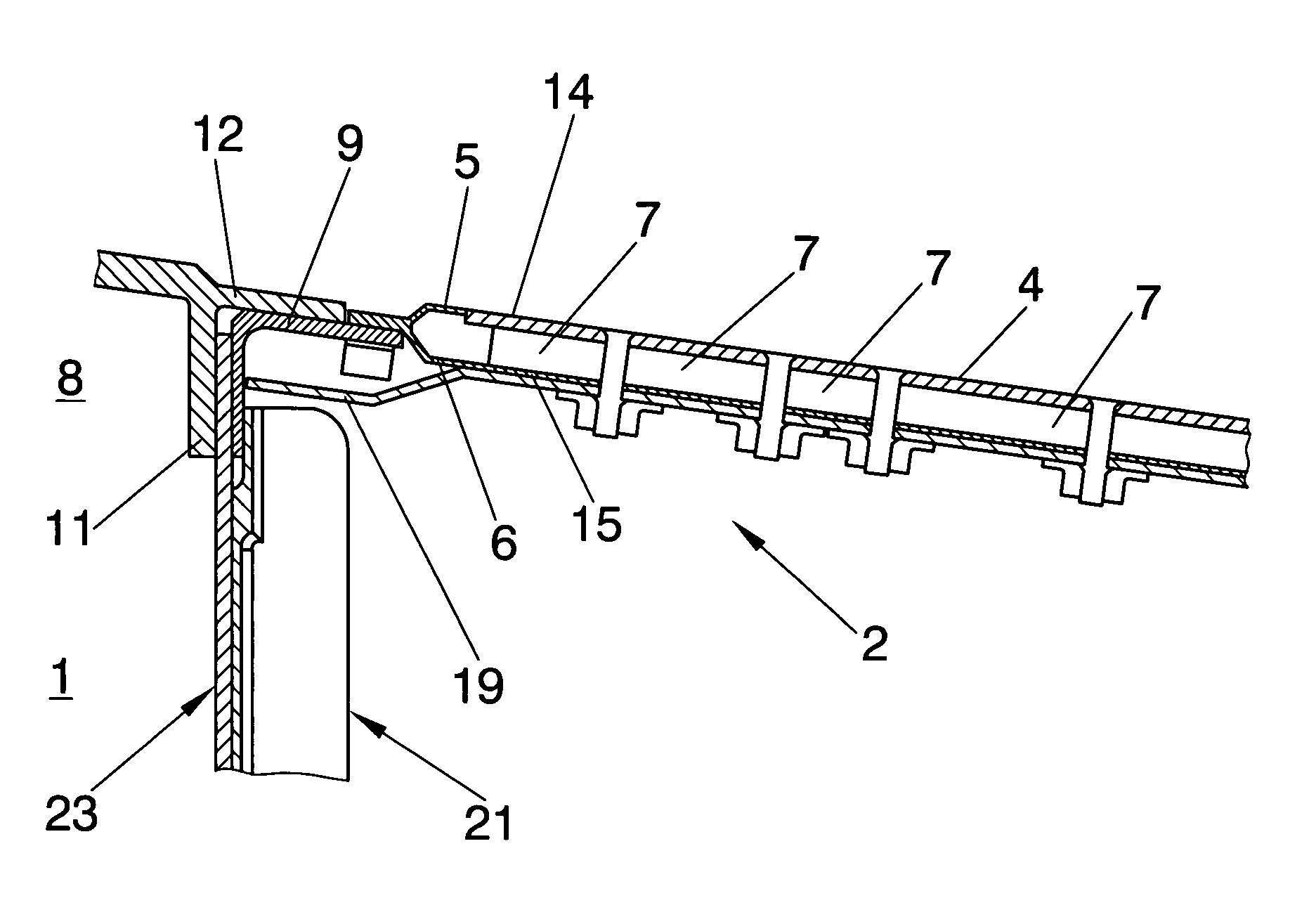
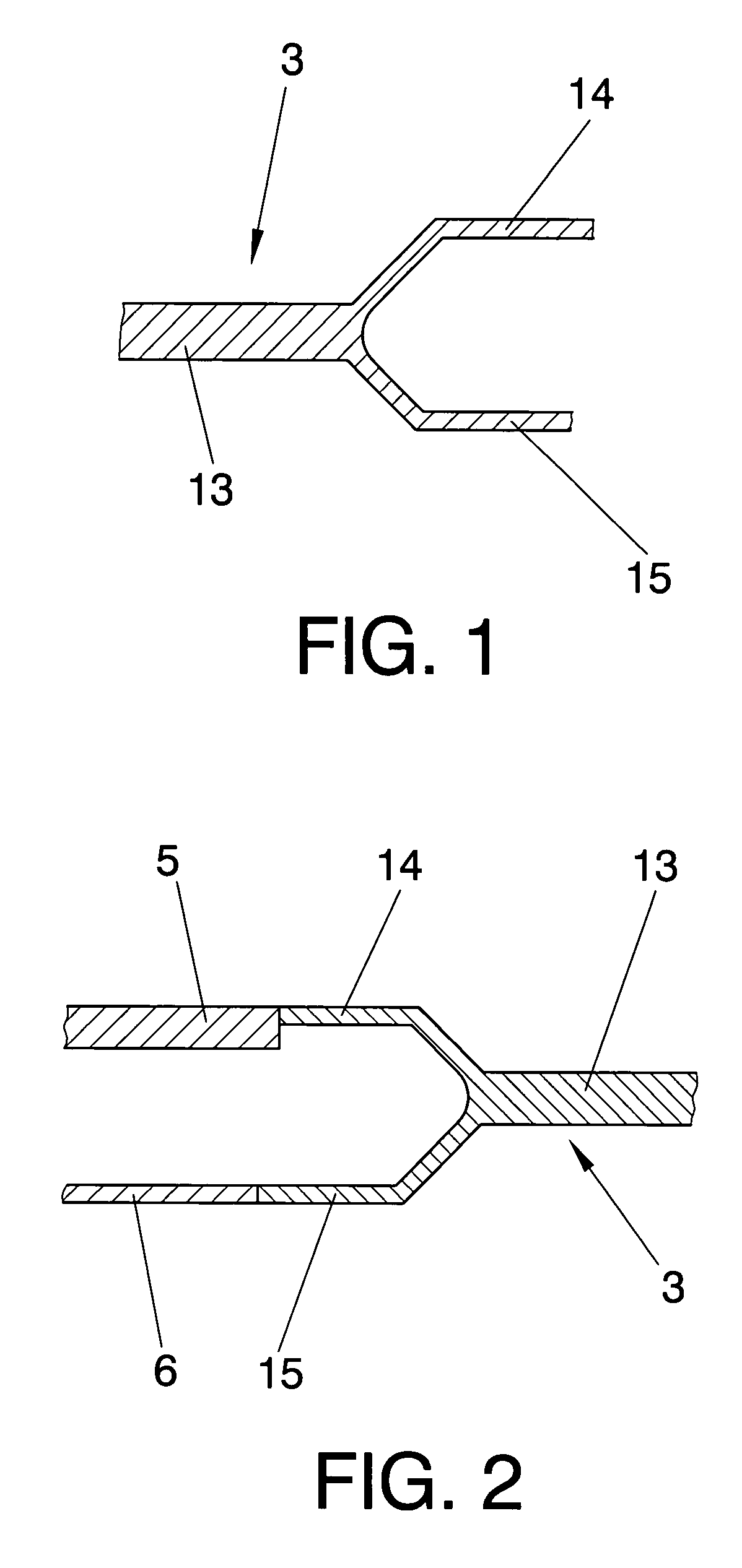
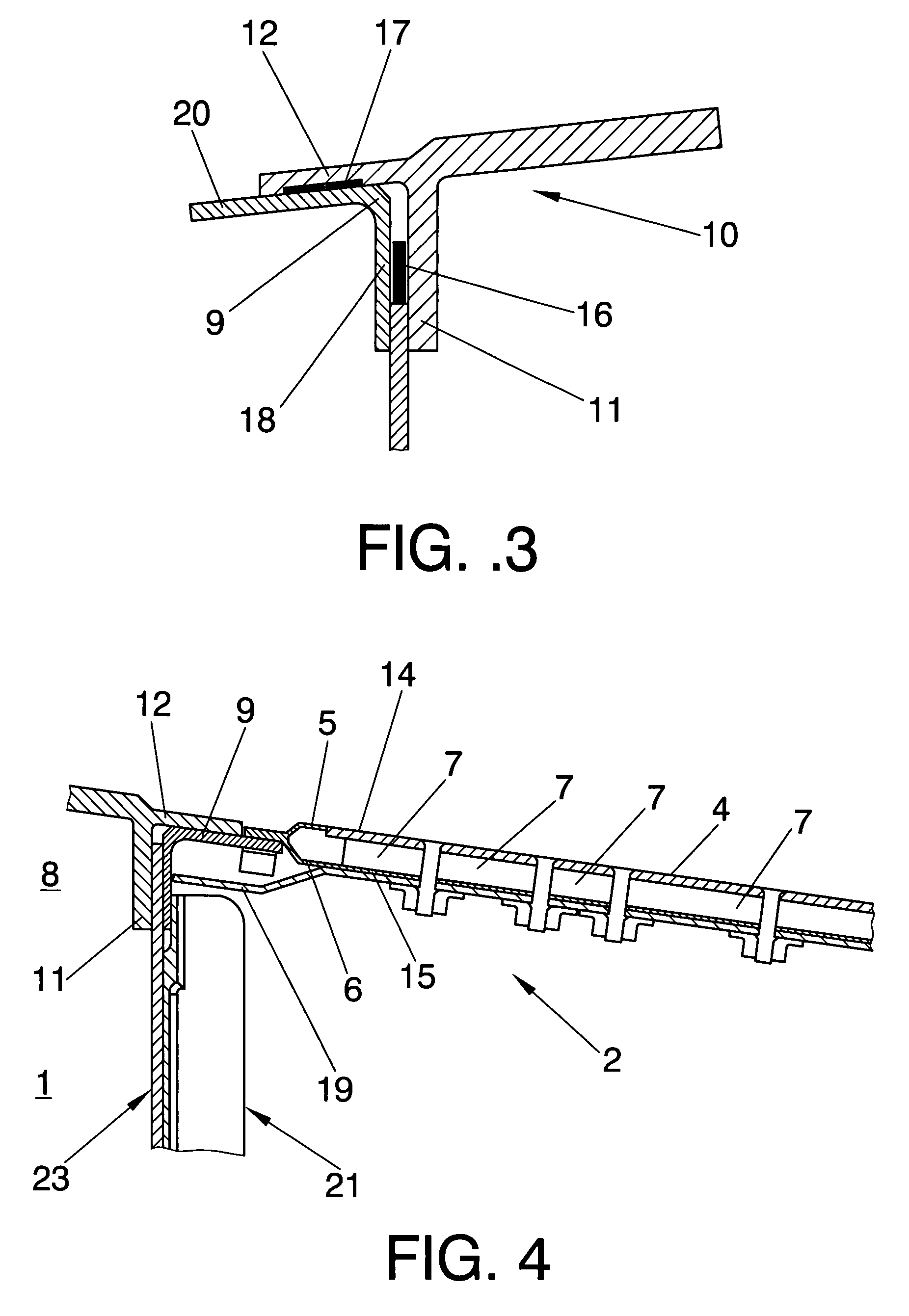
[0012]The leading edge sought to be fixed to the structure of a lift plane by means of the present invention comprises a covering formed from a first lamina and a second lamina which house inside them an interior airtight chamber divided into a plurality of suction chambers. The leading edge also comprises a...


PUM


Abstract

Fixing system for a modular leading edge (2) to the structure of an aircraft lift plane (1), in which the leading edge (2) has a covering (4) formed from a first lamina (5) and a second lamina (6) between which there is an interior airtight chamber, and the fixing system comprises a main attachment element (3) whose cross-section has a central element (13), a first arm (14) which is fixed to the first lamina (5) of the covering (4) of the leading edge (2), and a second arm (15) which is fixed to the second lamina (6) of the covering (4), and the central element (13) is in turn fixed to a covering (10) of the torsion box (8) of the structure of the lift plane (1).

Description

TECHNICAL FIELD OF THE INVENTION[0001]This invention belongs to the technical field of fixing systems for leading edges to surfaces in the aeronautical sector, and more particularly to the field of fixing systems for leading edges to the structure of an aircraft lift plane, and more particularly yet to the fixing of leading edges to the structure of a stabiliser.STATE OF THE PRIOR ART OF THE INVENTION[0002]In the great majority of aerodynamic surfaces, such as aircraft lift planes or stabilisers, it is desirable to fix a leading edge to the structure of those aerodynamic surfaces in order to improve the aerodynamic properties of the surface, causing the flow exterior to that leading edge to be laminar and decreasing as far as possible the aerodynamic resistance existing in flying conditions, thus achieving a reduction in fuel consumption with the saving and preservation of the environment that this implies, in addition to less wear and deterioration of the mechanical structures.[000...

Claims


Application Information

Patent Timeline
Patent Type & Authority Patents(United States)
IPC IPC(8): B64C21/06
CPCB64C3/28B64C2003/146B64C3/26B64C21/06
Inventor PEREZ RODRIGUEZ, DAVIDBALLESTERO MENDEZ, JORGE
Owner AIRBUS OPERATIONS SL
Why Eureka
Try Eureka