Connecting structure for hollow member or half hollow member

a technology of connecting structure and hollow member, which is applied in the direction of couplings, rod connections, jet propulsion mountings, etc., can solve the problems of time and effort, and achieve the effect of reducing construction elements and fixing collars easily and reliably

Active Publication Date: 2010-08-10
NISSAN MOTOR CO LTD +1
View PDF22 Cites 35 Cited by
  • Summary
  • Abstract
  • Description
  • Claims
  • Application Information

AI Technical Summary

Benefits of technology

[0006]It is an object of the present invention to provide a connecting structure for a hollow member or a half hollow member, devised to reduce constructional elements and to fix the collar easily and reliably.

Problems solved by technology

However in the case of above Japanese Patent Application, an expense in time and effort is necessary at the time of attachment of the collar; since the collar is inserted through the hollow member or the brackets provided to straddle the hollow member, and then is welded.
Moreover, the structure in which the hollow member is connected with the other member by inserting the bolt through the collar passing through the hollow member is not a structure constructed for solidly fixing the hollow member, since only the collar is in contact with the other member.

Method used


Image

  • Connecting structure for hollow member or half hollow member
  • Connecting structure for hollow member or half hollow member
  • Connecting structure for hollow member or half hollow member

Examples


first embodiment

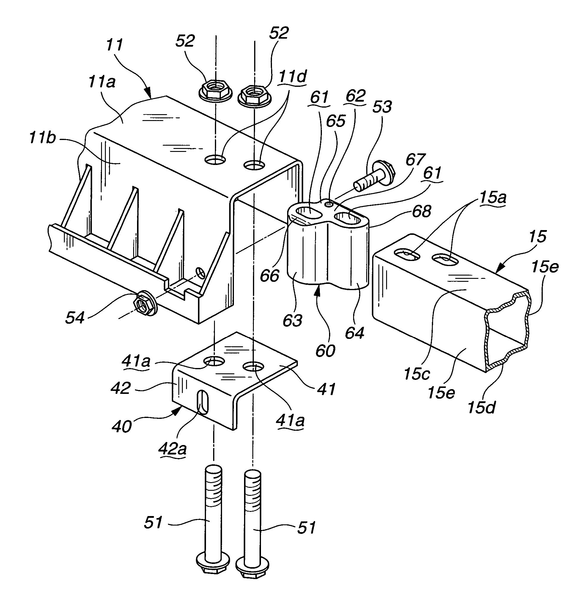
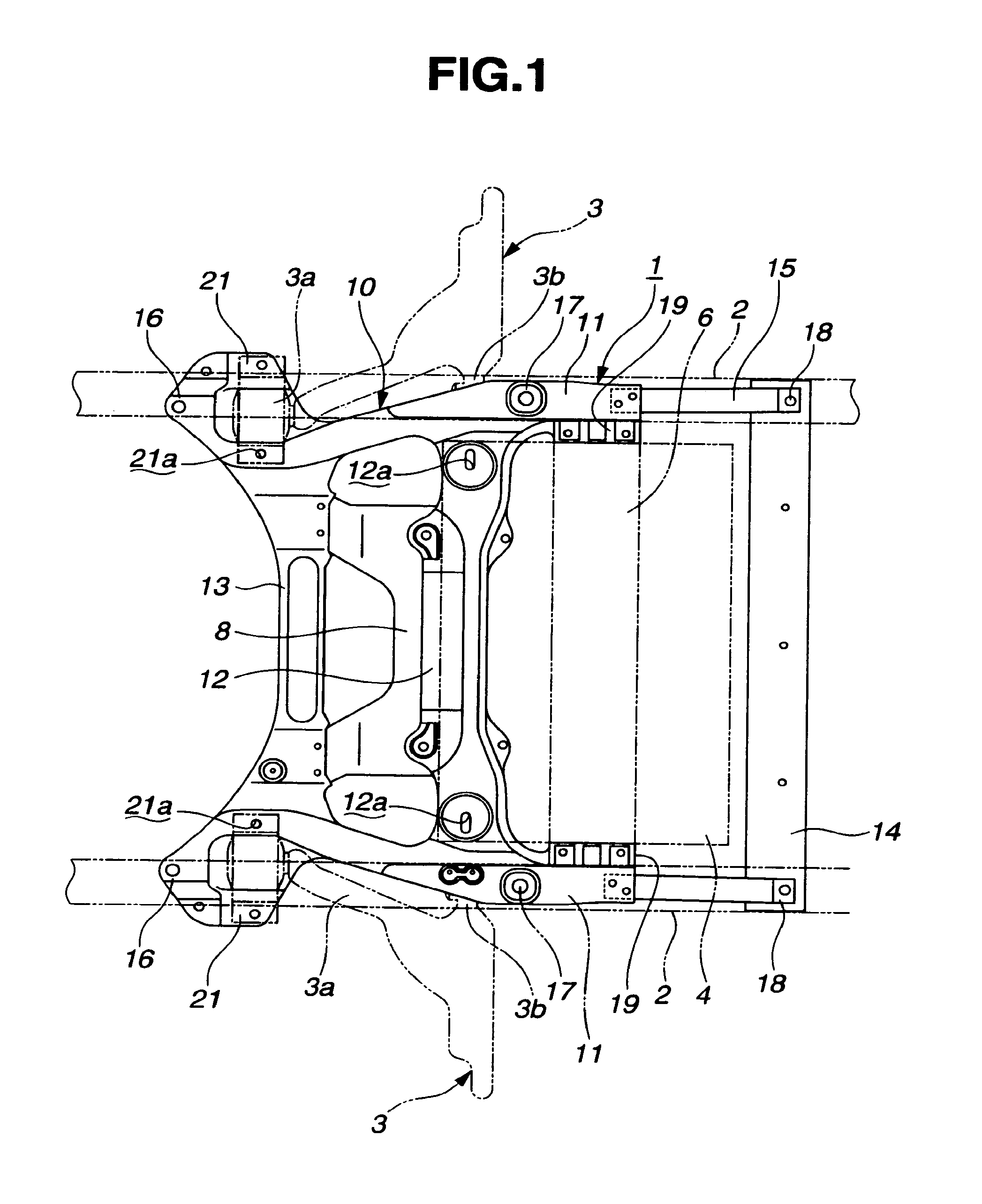
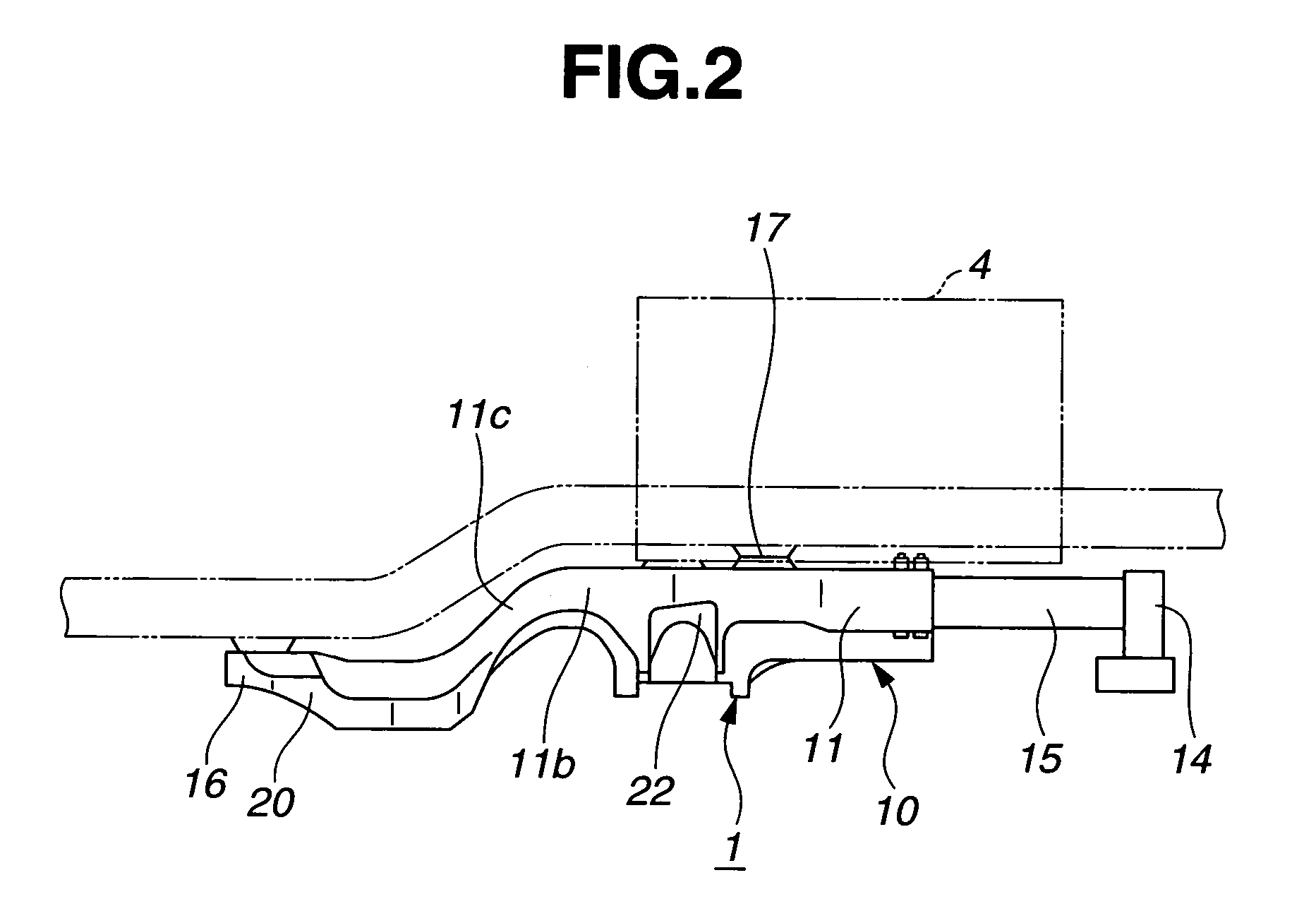
[0034]At first, a first embodiment according to the present invention will now be explained. FIG. 1 is a plan view showing a suspension member of an automotive vehicle, to which a connecting (coupling) structure for a hollow member or the like is applied according to the first embodiment. FIG. 2 is a side view of the suspension member shown in FIG. 1. FIG. 3 is a bottom view of the suspension member shown in FIG. 1. FIG. 4 is a bottom and oblique perspective view showing a supporting portion for a lower arm of a suspension arm and showing a coupling portion between a vehicle body (main frame) and a rear end portion of a side member, in this embodiment. FIG. 5 is an enlarged side view of FIG. 4. FIG. 7A is a partially cross-sectional view showing an enlarged part of FIG. 1. FIG. 7B is a cross-sectional view taken along a section line III-III of FIG. 7A. In this embodiment, a structural member having a rectangular and closed cross-section is employed as one example of the hollow membe...

second embodiment

[0090]A second embodiment according to the present invention will now be explained. At first, a configuration according to this embodiment will now be explained with reference to FIGS. 19-23. In this embodiment, a mounting structure of a bumper supporting member for a front bumper will be explained as one example of a mounting structure for bumper supporting member. However, the mounting (or connecting) structure for bumper supporting member in this embodiment is not limited to this, and also applicable to a mounting structure of a bumper supporting member for a rear bumper. In the examples of FIGS. 19-23, UD represents an upper direction in relation to a vehicle, LD represents a lower direction in relation to a vehicle, FD represents a front direction in relation to a vehicle, RD represents a rear direction in relation to a vehicle, and VWD represents a vehicle width direction in relation to a vehicle.

[0091]As shown in FIG. 19, in the mounting structure of bumper supporting member ...


PUM


Abstract

A connecting structure includes a hollow member or a half hollow member including two side portions opposed apart to each other; a collar; and a bolt. The collar includes two contact surfaces at both ends of the collar. The two contact surfaces are adapted to respectively abut on the two side portions between the two side portions. At least one of the two contact surfaces is formed with a receiving portion for caulking. Moreover, the collar is formed with a bolt-hole passing through the two contact surfaces. The collar is disposed between the two side portions, and is caulked with the hollow member or half hollow member at a caulked portion formed from at least one of the two side portions toward the receiving portion. The bolt is adapted to pass through the two side portions and the bolt-hole to connect the hollow member or half hollow member with another member.

Description

BACKGROUND OF THE INVENTION[0001]The present invention relates to a connecting structure and / or method for a hollow member or a half hollow member, more particularly relates to a connecting structure in which a bolt and a nut are used for fixing a hollow member or a half hollow member to the other member(s).[0002]Generally, in the case where a hollow member or half hollow member is fixed with the other member by a nut and a bolt having the length capable of passing through opposed two side portions of the hollow member or half hollow member, the hollow member or half hollow member is fixed with the other member by using a collar interposed between the two side portions of the hollow member or half hollow member. This is conducted in order not to vary a space (distance) between the two side portions of the hollow member or half hollow member due to a fastening force of the nut and bolt.[0003]Japanese Patent Application Publication No. 2000-238657 discloses a connecting structure in w...

Claims


Application Information

Patent Timeline
Patent Type & Authority Patents(United States)
IPC IPC(8): F16B7/10B60G7/02
CPCB62D21/09B62D21/11B62D27/065B62D21/155Y10T403/7079Y10T403/7084
Inventor ANZAI, EIJIYAMADA, YUNOSUKEKONNO, YOSHIHIROMURAYAMA, YUKI
Owner NISSAN MOTOR CO LTD
Why Eureka
Try Eureka