Electrical panel having electrically isolated neutral stab

a technology of neutral brackets and electrical panels, which is applied in the direction of protective switch details, relays, transportation and packaging, etc., can solve the problems of undesirable system configurations of this type (known as “non-separately derived systems”), and achieve the effect of being easily adaptable to an electrical panel

Active Publication Date: 2010-08-10
RELIANCE CONTROLS
View PDF2 Cites 15 Cited by
  • Summary
  • Abstract
  • Description
  • Claims
  • Application Information

AI Technical Summary

Benefits of technology

[0010]It is an object of the present invention to provide a neutral bracket apparatus that can be readily adapted to an electrical panel. It is another object of the present invention to provide a neutral bracket apparatus configured to connect a pair of opposed single-pole transfer switch assemblies in electrical connection with neutral conductors associated with a generator and a utility service, respectively, to provide alternative sources of electrical power to the electrical panel.

Problems solved by technology

However, this configuration, known as a “non-separately derived system”, has drawbacks when used with bonded-neutral generators.
It is this undesired dual path for electrical current to follow back from the load to the generator that creates a problem.
Thus, system configurations of this type (known as “non-separately derived” systems”) are undesirable because such configurations allow a normal flow of electrical current to pass via the neutral conductor of the building to the safety grounding conductor of the generator.
Another drawback of above-described known system configurations is that the flow of electrical current to the safety grounding conductor of the generator has been known to trigger a ground fault circuit interrupter at the generator.

Method used


Image

  • Electrical panel having electrically isolated neutral stab
  • Electrical panel having electrically isolated neutral stab
  • Electrical panel having electrically isolated neutral stab

Examples


Embodiment Construction

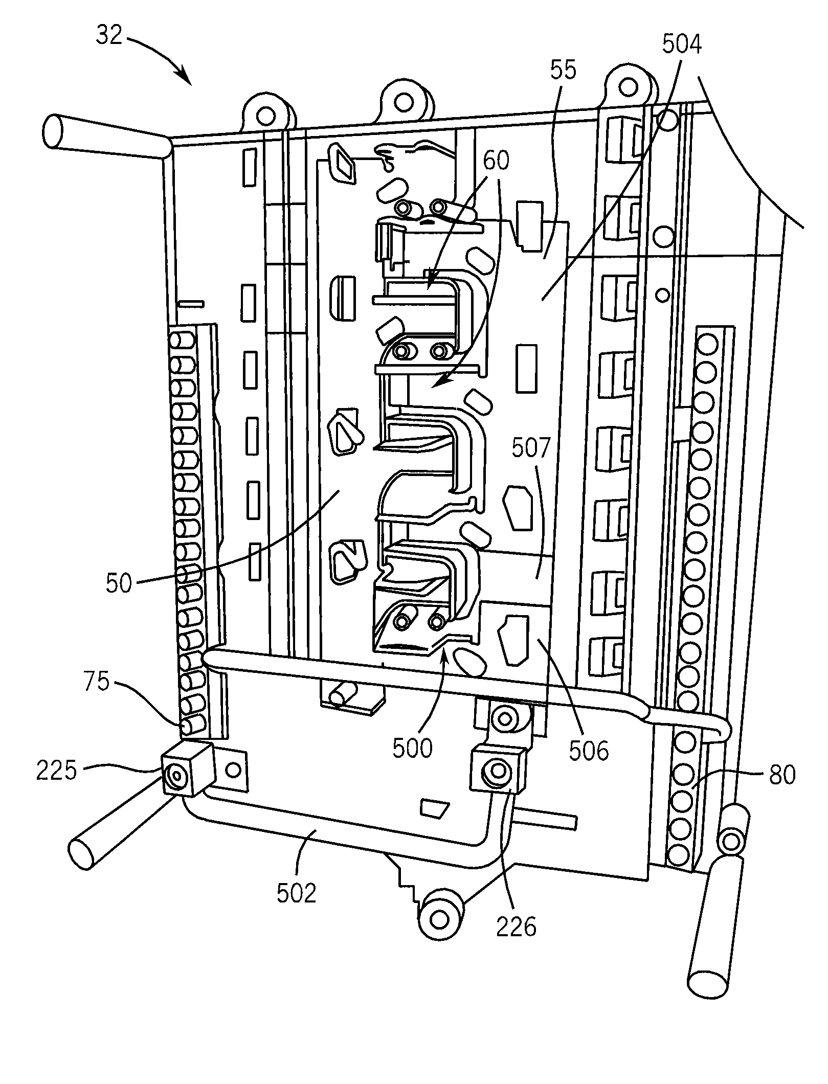
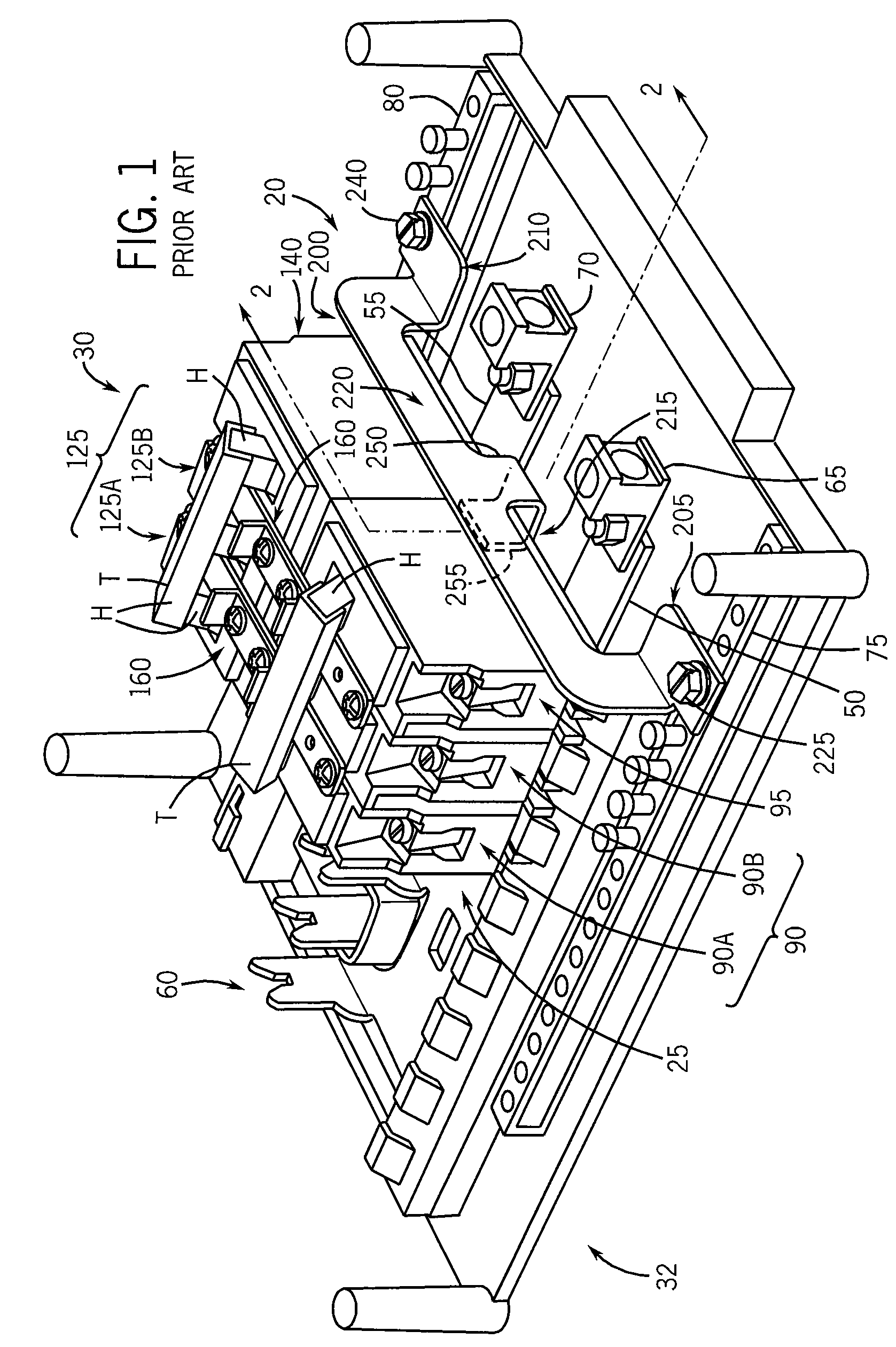
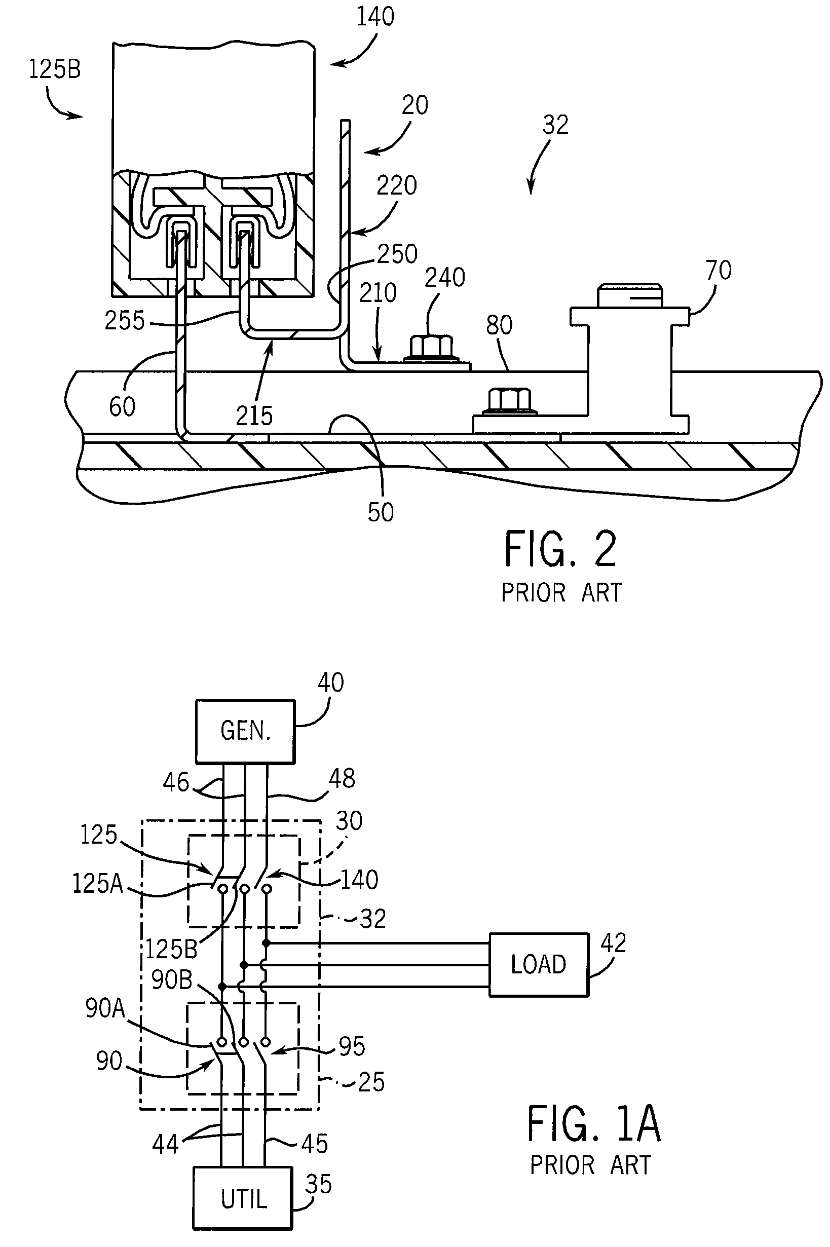
[0029]FIG. 1 illustrates a preferred embodiment of neutral bracket apparatus 20 in accordance with the present invention. Neutral bracket apparatus 20 is mounted to a conventional load center or electrical panel 32, in combination with a pair of opposed switch assemblies 25 and 30. FIG. 1A is a general schematic diagram that illustrates the electrical circuitry of the electrical panel 32, which is generally configured to switch the supply electrical power between a utility service 35 and a generator 40 to an electrical load 42. The utility service 35 generally includes a pair of “hot” line conductors 44 and a neutral conductor 45 in electrical connection with the first switch assembly at the electrical panel 32. In a similar manner, the generator 40 includes a pair of “hot” line conductors 46 and a neutral conductor 48 in electrical connection with the second switch assembly 30 at the electrical panel 32.

[0030]Referring to FIG. 1, the electrical panel 32 includes a single-phase pane...


PUM


Abstract

An electrical panel is operable to receive electrical power from a first power supply and a second power supply. The electrical panel includes a neutral bus conductor having a stab configured to engage one or more switching devices and a separation formed in a bus conductor to electrically isolate one of the stabs.

Description

FIELD OF THE INVENTION[0001]This invention relates to a neutral bracket apparatus for an electrical panel, and more specifically, to a neutral bracket apparatus configured to provide electrical connection between a pair of opposed neutral transfer switch assemblies and a pair of opposed neutral side bars mounted on the electrical panel.BACKGROUND OF THE INVENTION[0002]In today's electrical supply systems, there are occasions when alternate sources of electrical power are necessary or desirable. For example, the capability of switching from utility power to emergency generator power is extremely important for many businesses, hospitals and industries, as well as residential dwellings.[0003]In certain applications, it is desirable for separate electrical circuits, or separate groups of electrical circuits, to be arranged so that when one circuit or group of circuits is switched to a conductive state, another circuit or group of circuits is switched to a non-conductive state in an alte...

Claims


Application Information

Patent Timeline
Patent Type & Authority Patents(United States)
IPC IPC(8): H01H47/00
CPCH02B1/056H01H71/002H01H71/082H01H71/1018H01R9/2675
Inventor FLEGEL, DAVID D.
Owner RELIANCE CONTROLS
Why Eureka
Try Eureka