Load control device for use with lighting circuits having three-way switches
a technology of load control device and lighting circuit, which is applied in the direction of relays, contact mechanisms, sustainable buildings, etc., can solve the problems of increasing the cost of components and the installation of dimming systems, the inability of the smart dimmer to provide the advanced set of features of the smart dimmer to the end user, and the inability of the smart dimmer to work properly with the existing mechanical three-way or four-way switch
- Summary
- Abstract
- Description
- Claims
- Application Information
AI Technical Summary
Benefits of technology
Problems solved by technology
Method used
Image
Examples
second embodiment
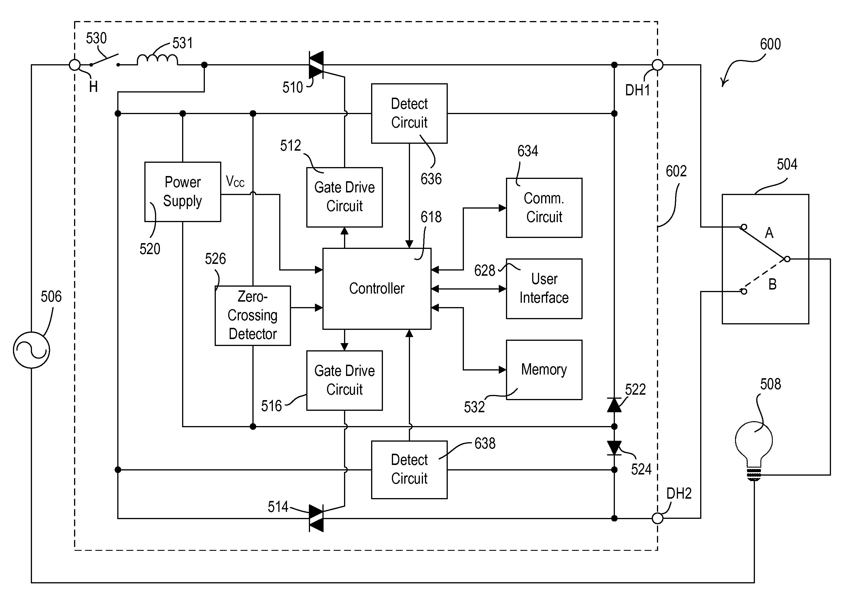
[0074]FIG. 6A shows a simplified block diagram of a three-way lighting control system 600 including a smart three-way dimmer switch 602 according to the present invention. A first detect circuit (or sensing circuit) 636 is coupled across the first triac 510 and a second detect circuit (or sensing circuit) 638 is coupled across the second triac 514. The detect circuits 636, 638 provide control signals to the controller 618 representative of electrical characteristics of the first dimmed hot terminal DH1 and the second dimmed hot terminal DH2, respectively. Each of the electrical characteristics may be a voltage developed across one of the respective triacs. Alternatively, the detect circuits 636, 638 may be placed in series with the dimmed hot terminals DH1, DH2 and the electrical characteristics may be currents through the dimmed hot terminals. In essence, the sensing of the electrical characteristics provides a determination of whether a path of continuity exists between hot and ne...
third embodiment
[0081]FIG. 7A shows a simplified block diagram of a three-way lighting control system 700 including a smart three-way dimmer switch 702 according to the present invention. In this embodiment, the dimmer switch 702 includes a single controllably conductive device, for example, a bidirectional semiconductor switch, such as a triac 710. A controller 714 is coupled to the gate of the triac 710 through a gate drive circuit 712 and controls the conduction time of the triac each half-cycle. A power supply 716 is coupled across the triac 710 and generates a DC voltage VCC to power the controller 714. A zero-crossing detector 718 determines the zero-crossing points of the AC voltage source 506 and provides this information to the controller 714. A user interface 720 provides inputs to the controller 714 from a plurality of buttons (including a toggle button) and includes a plurality of LEDs for feedback to a user. A communication circuit 722 allows the controller 714 to transmit and receive ...
fourth embodiment
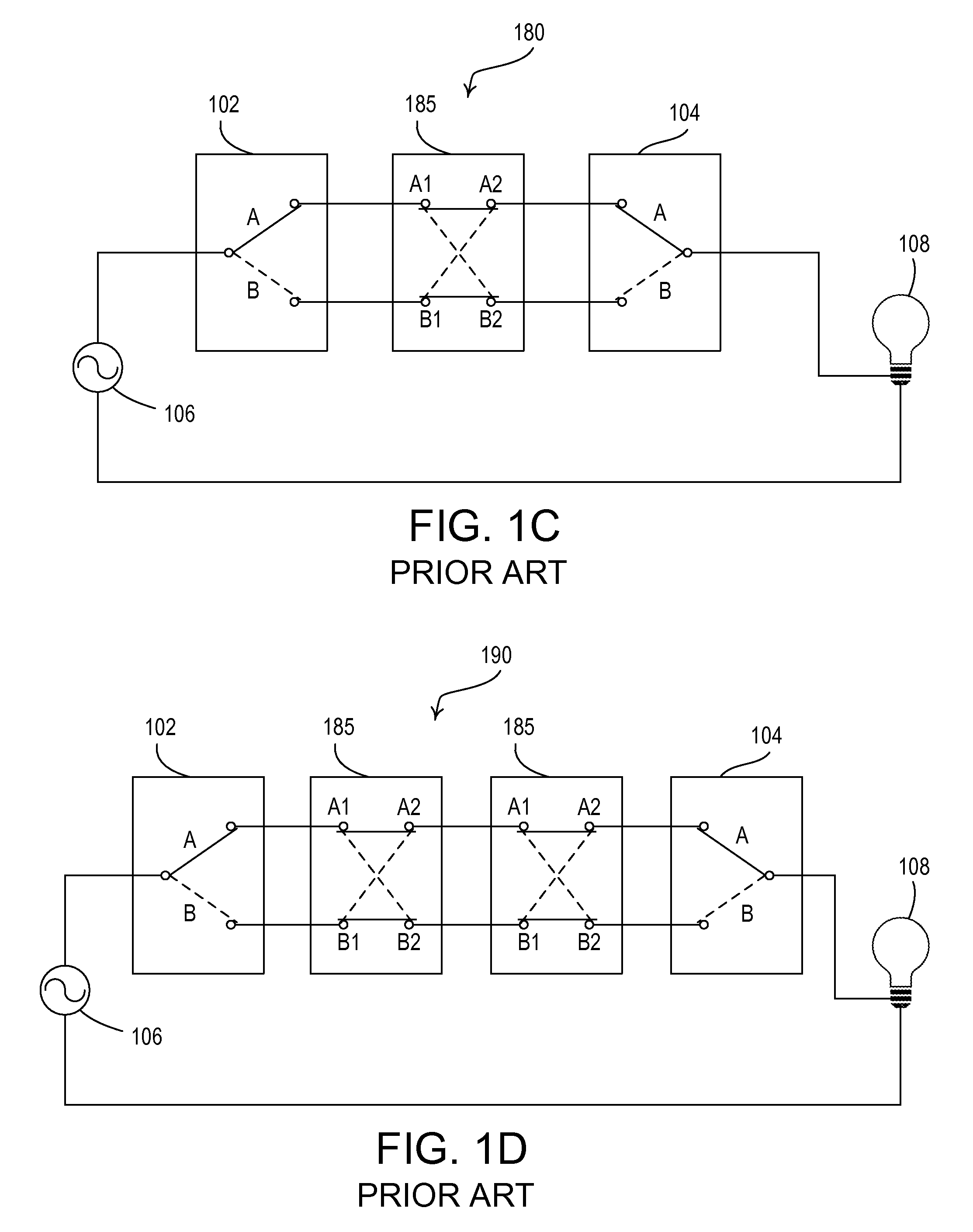
[0086]FIG. 8 is a simplified block diagram of a four-way lighting control system 800 including a smart four-way dimmer switch 802 according to the present invention. The dimmer 802 and two three-way switches 803, 804 are coupled between an AC voltage source 806 and a lighting load 808. The dimmer 802 has replaced the four-way switch 185 in the four-way lighting control system 180 of FIG. 1C.
[0087]The dimmer 802 operates on the same principles as the dimmer 702 of FIG. 7A. However, the dimmer 802 includes an additional hot terminal H2 that is coupled to the three-way switch 803 on the line-side of the system 802. The dimmer 802 further comprises a second current detect circuit (sensing circuit) 829 that is coupled between the hot terminals H, H2 and provides a signal to a controller 814. The second current detect circuit 829 operates in the same manner as the first current detect circuit 728. When current is detected flowing through the second current detect circuit 829, the controll...
PUM
 Abstract
Description
Claims
Application Information
 - R&D
- Intellectual Property
- Life Sciences
- Materials
- Tech Scout
- Unparalleled Data Quality
- Higher Quality Content
- 60% Fewer Hallucinations
Browse by: Latest US Patents, China's latest patents, Technical Efficacy Thesaurus, Application Domain, Technology Topic, Popular Technical Reports.
© 2025 PatSnap. All rights reserved.Legal|Privacy policy|Modern Slavery Act Transparency Statement|Sitemap|About US| Contact US: help@patsnap.com


