Gloss difference control in a plurality of networked image forming apparatus

a networked image and control function technology, applied in the field of image forming apparatus, can solve the problems of large tendency of temperature drop, time delay for heat to reach the fixing roller surface, and inability to achieve gloss difference in output image among each image forming apparatus

Active Publication Date: 2010-08-10
KONICA MINOLTA BUSINESS TECH INC
View PDF13 Cites 8 Cited by
  • Summary
  • Abstract
  • Description
  • Claims
  • Application Information

AI Technical Summary

Problems solved by technology

However, when a color image forming apparatus is used, fixing properties are influenced by a fluctuation of components accuracy due to a wear of the components, temperature control accuracy and the like, and thereby there is a possibility of having a deficiency that is a gloss difference in an output image among each image forming apparatus.
Even in a case of singularly using an image forming apparatus, when image formations are continuously performed, while a temperature controlling unit controls the image forming apparatus to return to an initial temperature, there is a time delay for a heat to reach a fixing roller surface from a heat source.
In particular, in a case of using an image forming apparatus having large number of copying pages per unit time, there is a large tendency of decreasing a temperature due to an insufficient heat supply.
Further, in addition to a preset temperature, according to a fluctuation of adding pressure by a heating roller and by a pressure roller, a fluctuation of a hardness of the heating roller, an error of a rotation speed of both the rollers and the like, an error in fixing properties may be generated for each image forming apparatus to be used, whereby there is a case of generating a gloss difference in an output image.
These deficiencies occur due to the fact that a toner for forming a color image has a large physical dependence on a heat and a pressure, compared to a toner for forming a monochrome image.
However, since it is necessary to designate a specific image forming apparatus, an operation becomes more complicated and a flexibility of a gloss adjustment is decreased.

Method used


Image

  • Gloss difference control in a plurality of networked image forming apparatus
  • Gloss difference control in a plurality of networked image forming apparatus
  • Gloss difference control in a plurality of networked image forming apparatus

Examples


Embodiment Construction

[0022]Hereinafter, an embodiment relating to a glossiness adjusting method and an image forming apparatus in the present invention will be described with reference to the drawings.

[0023]First, a image forming apparatus relating to the embodiment will be described.

[0024]In descriptions of the embodiment, a technical scope of the present invention is not limited by terms used in the specification.

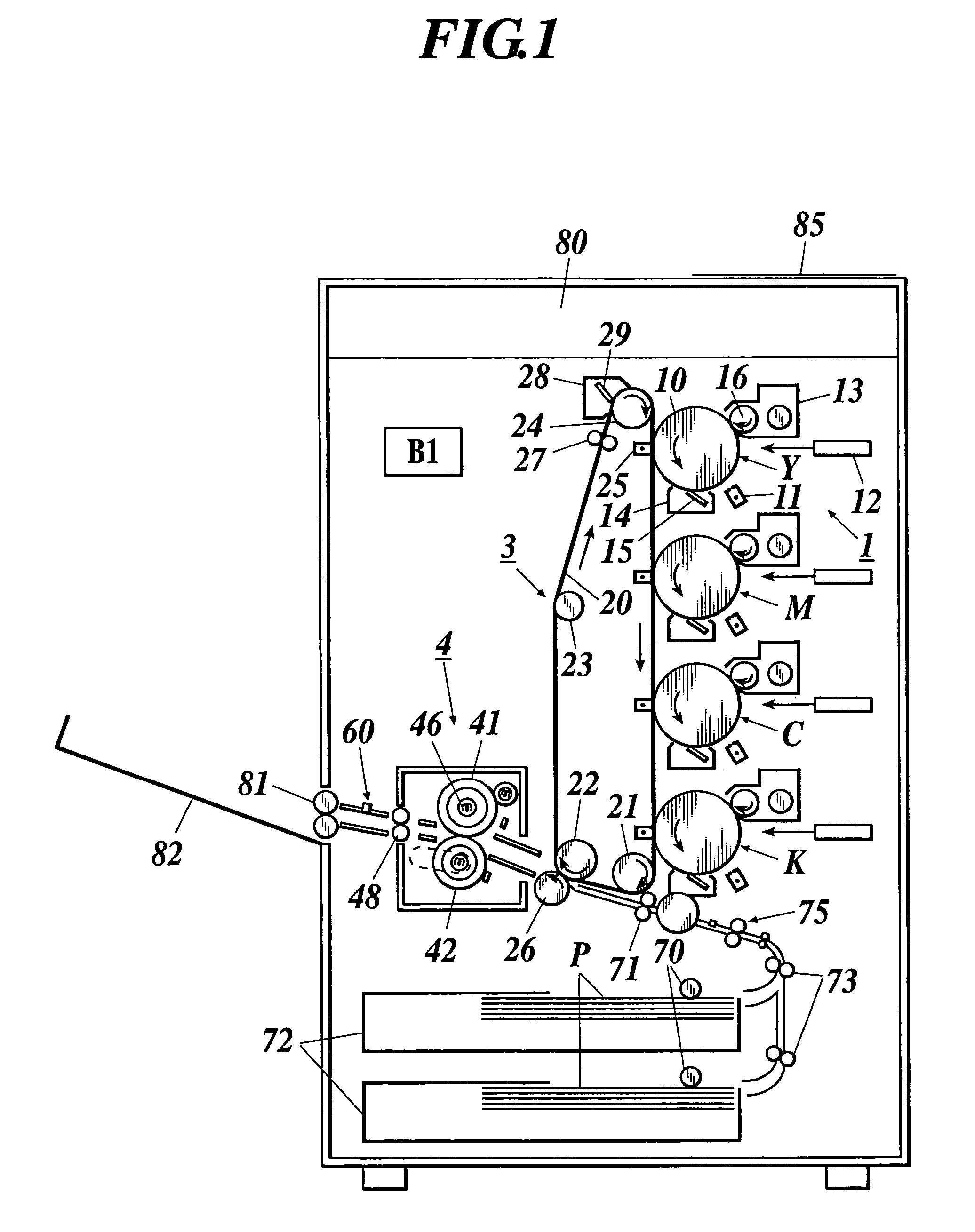
[0025]FIG. 1 is a pattern diagram showing one example of a whole structure of the image forming apparatus.

[0026]In FIG. 1, a photoreceptor 10; a scorotron electrifier 11, a writing device 12, a development device 13, a cleaning device 14 for cleaning a surface of the photoreceptor 10, a cleaning blade 15; a development sleeve 16, and an intermediate transfer belt 20 are shown. The image forming unit 1 comprises the photoreceptor 10, the scorotron electrifier 11, the development device 13, the cleaning device 14 and the like. Since a mechanical structure of the image forming unit 1 of each col...


PUM


Abstract

A gloss difference control method includes: forming a predetermined image on a sheet in each of a plurality of image forming apparatuses connected to a network; measuring a glossiness of the image formed on each sheet; and controlling a gloss difference among the plurality of image forming apparatuses by changing a gloss adjustment parameter of each of the plurality of image forming apparatuses, based on a plurality of the measured glossiness.

Description

BACKGROUND OF THE INVENTION[0001]1. Field of the Invention[0002]The present invention relates to an image forming apparatus with a heat fixing device for electrophotography process, such as a copier, a printer, a facsimile and the like. More specially, the present invention relates to an image forming apparatus with a gloss control function and gloss control method for an image forming apparatus.[0003]2. Description of Related Art[0004]These days, a system structure in which a plurality of image forming apparatuses are connected to a network for making a productivity thereof as number of times as that of a case of using an image forming apparatus in standalone mode is implemented. This system structure provides a better outputting speed and contributes to productivity. However, when a color image forming apparatus is used, fixing properties are influenced by a fluctuation of components accuracy due to a wear of the components, temperature control accuracy and the like, and thereby t...

Claims


Application Information

Patent Timeline
Patent Type & Authority Patents(United States)
IPC IPC(8): H04N1/29H04N1/32H04N1/40G06K15/14G03G15/20
CPCG03G15/0121G03G15/2064G03G15/5079G03G2215/0081G03G2215/00805
Inventor KATAYANAGI, HIDETOSHI
Owner KONICA MINOLTA BUSINESS TECH INC
Why Eureka
Try Eureka