Mop head connector

a technology of mop head and connector, which is applied in the direction of couplings, carpet cleaners, manufacturing tools, etc., can solve the problems of prone to loose threaded connection systems between the handle and the mop head, easy and effective connection, and easy and effective attachment. , the effect of simple and economical production

Inactive Publication Date: 2010-08-17
QUICKIE MFG
View PDF7 Cites 18 Cited by
  • Summary
  • Abstract
  • Description
  • Claims
  • Application Information

AI Technical Summary

Benefits of technology

[0004]It is an object of the present invention to provide a mop head connection system which ensures for a quick and easy attachment between the mop head and handle.
[0005]It is another object of the present invention to provide a mop connection system for ensuring that there is always a secure connection between the mop head and the handle, especially during prolonged use of the mop.
[0006]It is another object of the present invention to provide a mop head connection system which is simple and economical to produce and which has a limited number of connection components.
[0007]It is a further object of the present invention to provide a mop head connection system with an attachment element which provides an easy and effective connection between the mop head and mop handle.
[0008]It is still another object of the present invention to provide a mop head connection system which uses a resilient clip to quickly and securely connect the mop head to the mop handle.
[0009]These and other objects are accomplished by the present invention, a mop head connection system which has a handle connector component secured to the mop handle and a mop head connector component secured to the mop head. Through holes in the handle connector component are aligned with through holes in the mop head connector component. A resilient clip with protruding tabs is positioned in and around the mop head connector component, such that the tabs of the resilient clips extend through the aligned holes in the connector components. The resiliency of the clips compels the tabs into the holes, thus securing the components.

Problems solved by technology

In this manner, mop heads whose cleaning strands become old and ineffective can be discarded and new heads replaced on the mop handles.
However, this type of connection has several significant disadvantages.
The threaded connection system between a handle and a mop head is prone to becoming loose during prolonged use of the mop.
Also, repeatedly changing the mop head on the handle tends to cause the threads at the end of the handle to become worn and increasingly ineffective in securing the mop head.

Method used


Image

  • Mop head connector
  • Mop head connector
  • Mop head connector

Examples


Embodiment Construction

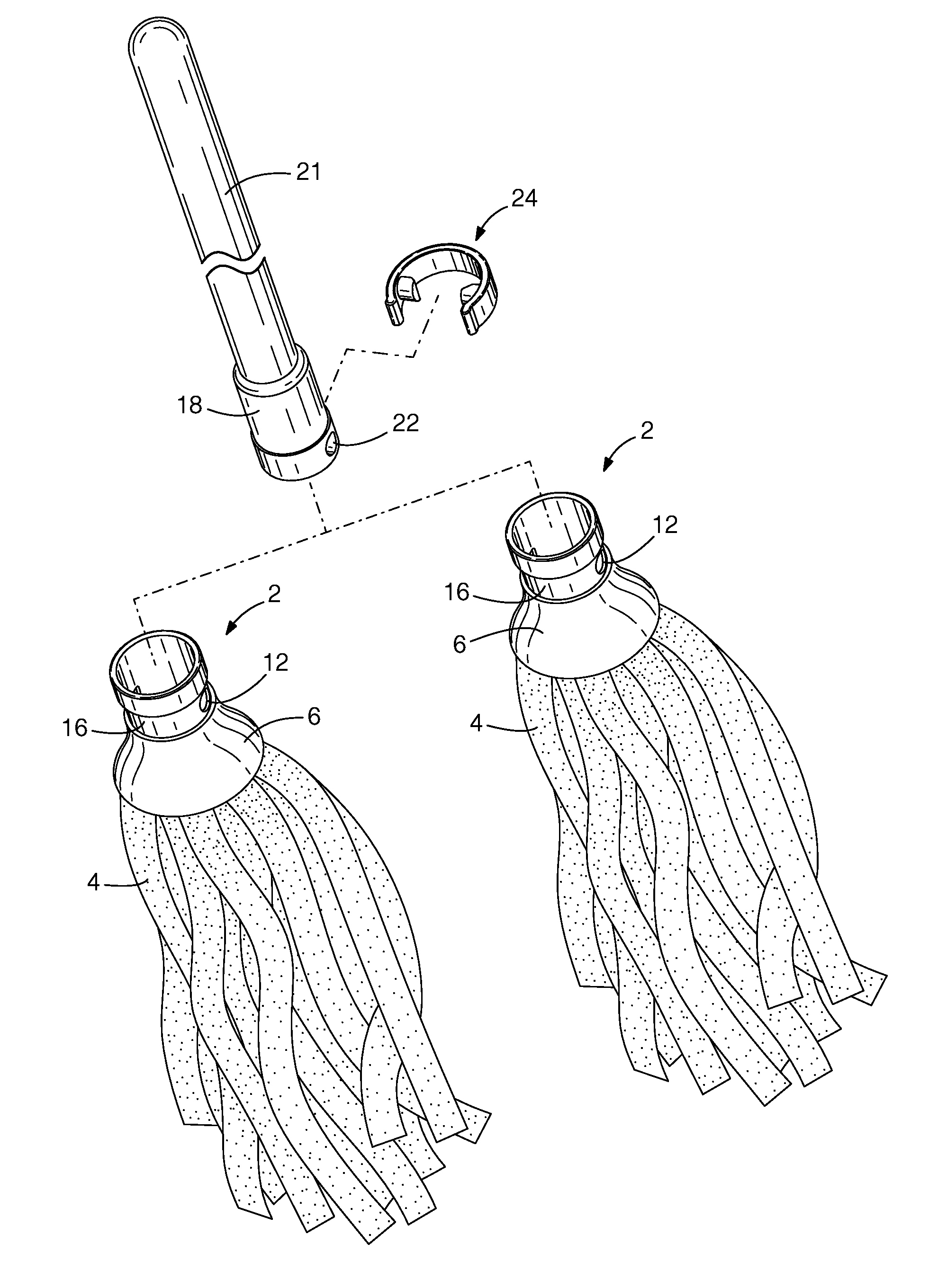
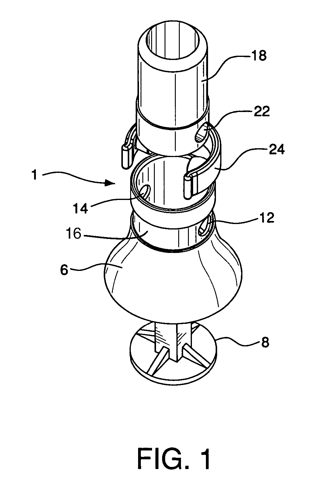
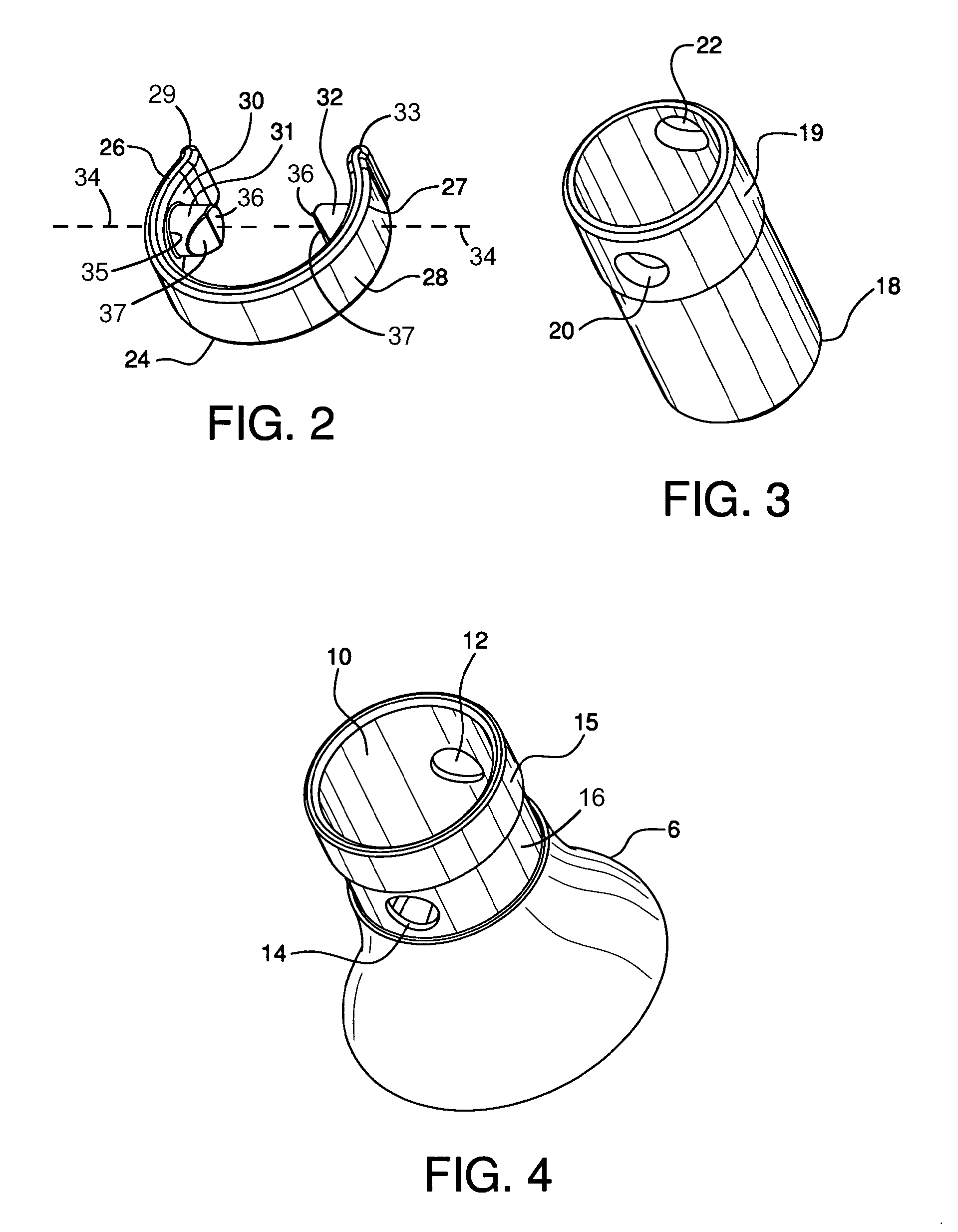
[0017]With reference to FIG. 1 the mop head connection system 1 of the present invention is used on a mop comprising mop head 2 with cloth strands 4 which are secured in conventional fashion to mop head connector component 6 via mop strand connector 8. Mop head connector 6 has opening 10 at its upper end section 15, a recess 16 defined in the upper end section 15, and through openings 12 and 14 disposed in the recess 16 and parallelly aligned on either side of the upper end section of the mop head connector. Mop handle 21 is permanently connected by pressure fitting, tacks, or other known means, to one end of handle connector component 18. Handle connector 18 is substantially cylindrical in configuration and, at its lower end 19, comprises through openings 20 and 22 parallelly aligned on opposite sides of the connector. As seen in FIG. 1, handle connector 18 is configured to be inserted into mop head connector 6, such that through holes 20 and 22 of handle connector 18 and through h...


PUM


Abstract

A connection system for securing a mop head to a mop handle. The system uses a handle connector component secured to the mop handle and a mop head connector component secured to the mop head. Through holes in the handle connector component are aligned with through holes in the mop head connector component. A resilient clip with protruding tabs is positioned in and around the mop head connector component, such that the tabs of the resilient clips extend through the aligned holes in the connector components. The resiliency of the clips compels the tabs into the holes, thus securing the components.

Description

BACKGROUND OF THE INVENTION[0001]The cleaning section of a mop, normally referred to as the mop head, is routinely secured to the mop's handle by a threaded connection, i.e. threads at the end of the handle are screwed into a threaded opening in the mop head. In this manner, mop heads whose cleaning strands become old and ineffective can be discarded and new heads replaced on the mop handles.[0002]However, this type of connection has several significant disadvantages. The threaded connection system between a handle and a mop head is prone to becoming loose during prolonged use of the mop. This requires constantly stopping the cleaning operation to tighten the handle / mop head connection. Also, repeatedly changing the mop head on the handle tends to cause the threads at the end of the handle to become worn and increasingly ineffective in securing the mop head.SUMMARY OF THE INVENTION[0003]Accordingly, it the object of the present invention to overcome the limitations and disadvantages...

Claims


Application Information

Patent Timeline
Patent Type & Authority Patents(United States)
IPC IPC(8): A47L13/42B25G3/12
CPCA47L13/24A47L13/42B25G3/26Y10T403/7077Y10T16/469Y10T403/60
Inventor WEAVER, JACE A.
Owner QUICKIE MFG
Why Eureka
Try Eureka