Cable tie with electrical connector fastener

a technology of electrical connectors and fasteners, which is applied in the field of cable ties, can solve the problems of high undesirable, bouncing and rattling, and the fastener disclosed in the '451 patent suffers from a notable drawback, and achieves the effect of convenient use and inexpensive manufacturing

Active Publication Date: 2010-08-17
AVERY DENNISON CORP
View PDF22 Cites 32 Cited by
  • Summary
  • Abstract
  • Description
  • Claims
  • Application Information

AI Technical Summary

Benefits of technology

[0012]It is still another object of the present invention to provide a cable tie of the type as described above which includes a limited number of parts, which is easy to use and which is inexpensive to manufacture.

Problems solved by technology

However, if a particular component is not installed in the vehicle, the unattached electrical connector remains loose within the automotive body, thereby rendering it susceptible to bouncing and rattling during operation of the vehicle, which is highly undesirable.
Although well known and widely used in commerce, the fastener disclosed in the '451 patent suffers from a notable drawback.
As a result, it has been found that the fastener disclosed in the '451 patent is incapable of being used with many common types of conventional electrical connectors, which is highly undesirable.

Method used


Image

  • Cable tie with electrical connector fastener
  • Cable tie with electrical connector fastener
  • Cable tie with electrical connector fastener

Examples


Embodiment Construction

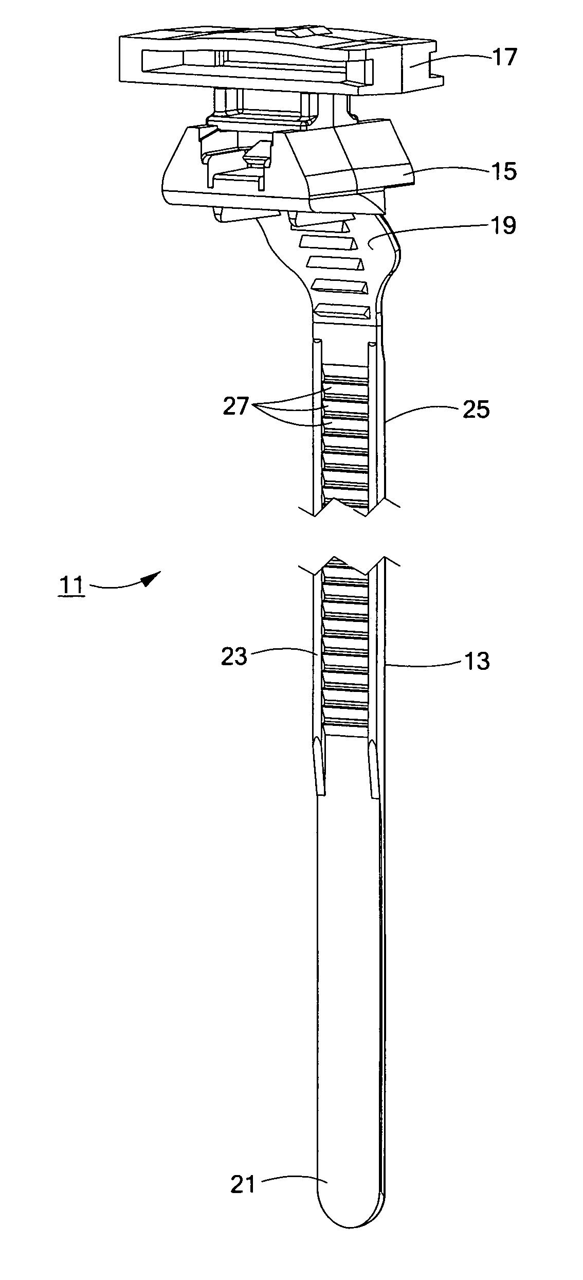
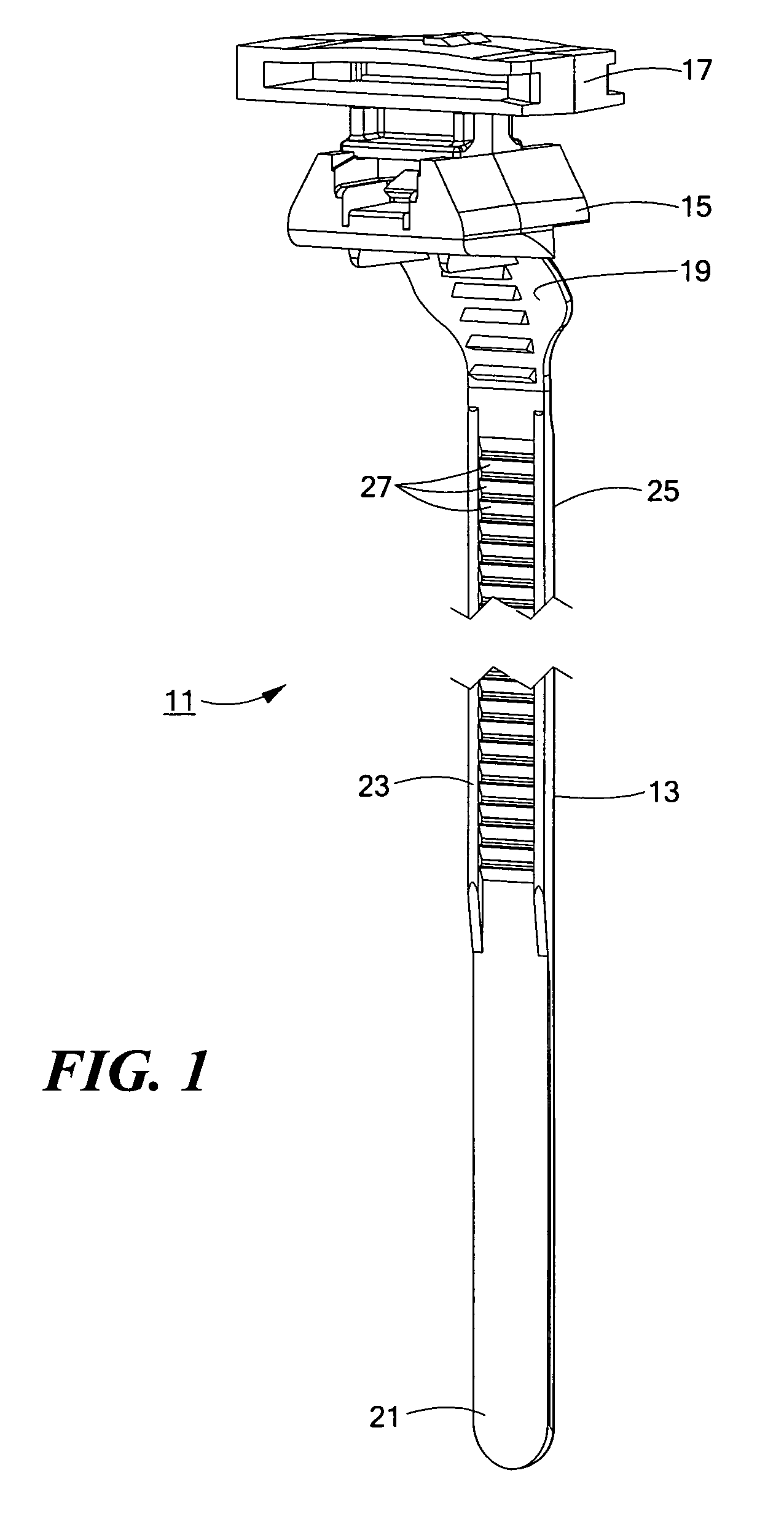
[0021]Referring now to FIG. 1, there is shown a front perspective view of a cable tie constructed according to the teachings of the present invention, the cable tie being identified generally by reference numeral 11. As will be described further in detail below, cable tie 11 is designed to both (i) wrap tightly around a bundle, such as a plurality of individual electrical wires, and (ii) fixedly secure a loose electrical connector against the cinched bundle.

[0022]Cable tie 11 is a one piece tie which includes an elongated strap 13, a locking head 15 and a fastener 17. Preferably, cable tie 11 is constructed from a durable and inexpensive material, such as plastic, nylon or a high modulus elastomer, using conventional molding techniques.

[0023]Elongated strap 13 is preferably flexible in nature and includes a first end 19, a second end 21, a front surface 23 and a bottom surface 25. A plurality of ratchet-shaped teeth 27 are integrally formed into front surface 23 along the majority o...


PUM


Abstract

A cable tie includes a serrated strap which is fitted to an apertured head. In use, the cable tie can be formed into closed loop around an electrical harness cable by inserting the serrated strap through the apertured head. The cable tie additionally includes a fastener which can be used to secure an unattached electrical connector securely against the electrical harness cable. The fastener comprises a rectangular platform that includes a convex outer wall and a flat inner wall that are partially separated by a transverse slot. The platform is shaped to define a pair of opposing, inwardly extending notches which enable the platform to be slid into engagement with corresponding railings formed on the electrical connector. A ratchet-shaped tooth is formed on the convex outer wall to engage a corresponding pawl formed on the electrical connector to lockably retain the fastener coupled to the electrical connector.

Description

CROSS-REFERENCE TO RELATED APPLICATIONS[0001]The present application claims the benefit under 35 U.S.C. 119(e) of U.S. provisional Patent Application Ser. No. 60 / 876,677, filed on Dec. 22, 2006, the disclosure of which is incorporated herein by reference.BACKGROUND OF THE INVENTION[0002]The present invention relates generally to cable ties and more particularly to cable ties that are designed for use in automotive applications.[0003]In the automotive industry, an electrical harness is commonly utilized to simplify the process of connecting various electrical components that are installed in a vehicle (e.g., a radio, lighter, headlights, etc.) with a designated power source, such as a car battery. The electrical harness commonly includes a plurality of bundled electrical wires and a plurality of electrical connectors that are electrically coupled to the wires at various locations along the length of the harness. As can be appreciated, the harness is typically constructed outside the ...

Claims


Application Information

Patent Timeline
Patent Type & Authority Patents(United States)
IPC IPC(8): F16L3/08
CPCB60R16/0215F16L3/2334H02G3/30
Inventor GUNZBURGER, PAUL
Owner AVERY DENNISON CORP
Why Eureka
Try Eureka