Electronic device case structure having function of ejecting peripheral device

a technology of electronic devices and peripheral devices, which is applied in the direction of coupling device connections, data recording, engagement/disengagement of coupling parts, etc., can solve the problems of difficult assembly, high cost, and relative difficulty in removing the tray, and achieves the effect of convenient ejection

Inactive Publication Date: 2010-08-17
WISTRON CORP
View PDF8 Cites 16 Cited by
  • Summary
  • Abstract
  • Description
  • Claims
  • Application Information

AI Technical Summary

Benefits of technology

[0011]By pressing the operation end of the driving member, the peripheral device is easily to be ejected from the accommodating slot. An additional structure on the peripheral device for being grasped by a user is not required, such that the appearance of peripheral device matches with the appearance design of the electronic device case structure, thereby achieving an effect of beautifying the appearance.

Problems solved by technology

However, the absence of such an outward protruding part makes it relatively difficult to remove the tray.
However, the handle recess is a structure protruding from the case body, and the appearance of the handle recess cannot be combined with the case body as a whole, thereby affecting an aesthetic of the case body.
However, a structure of the automatic assembling / disassembling device is much more complicated, so it is difficult to assemble or a cost is too high.
Therefore, how to solve the problem of extracting the removable peripheral device without affecting the appearance of the case body remains a technical problem.
The removable peripheral device in the art is hard to be removed from an electrical device or the electrical device equipped with the removable peripheral device has an undesirable appearance.

Method used


Image

  • Electronic device case structure having function of ejecting peripheral device
  • Electronic device case structure having function of ejecting peripheral device
  • Electronic device case structure having function of ejecting peripheral device

Examples


Embodiment Construction

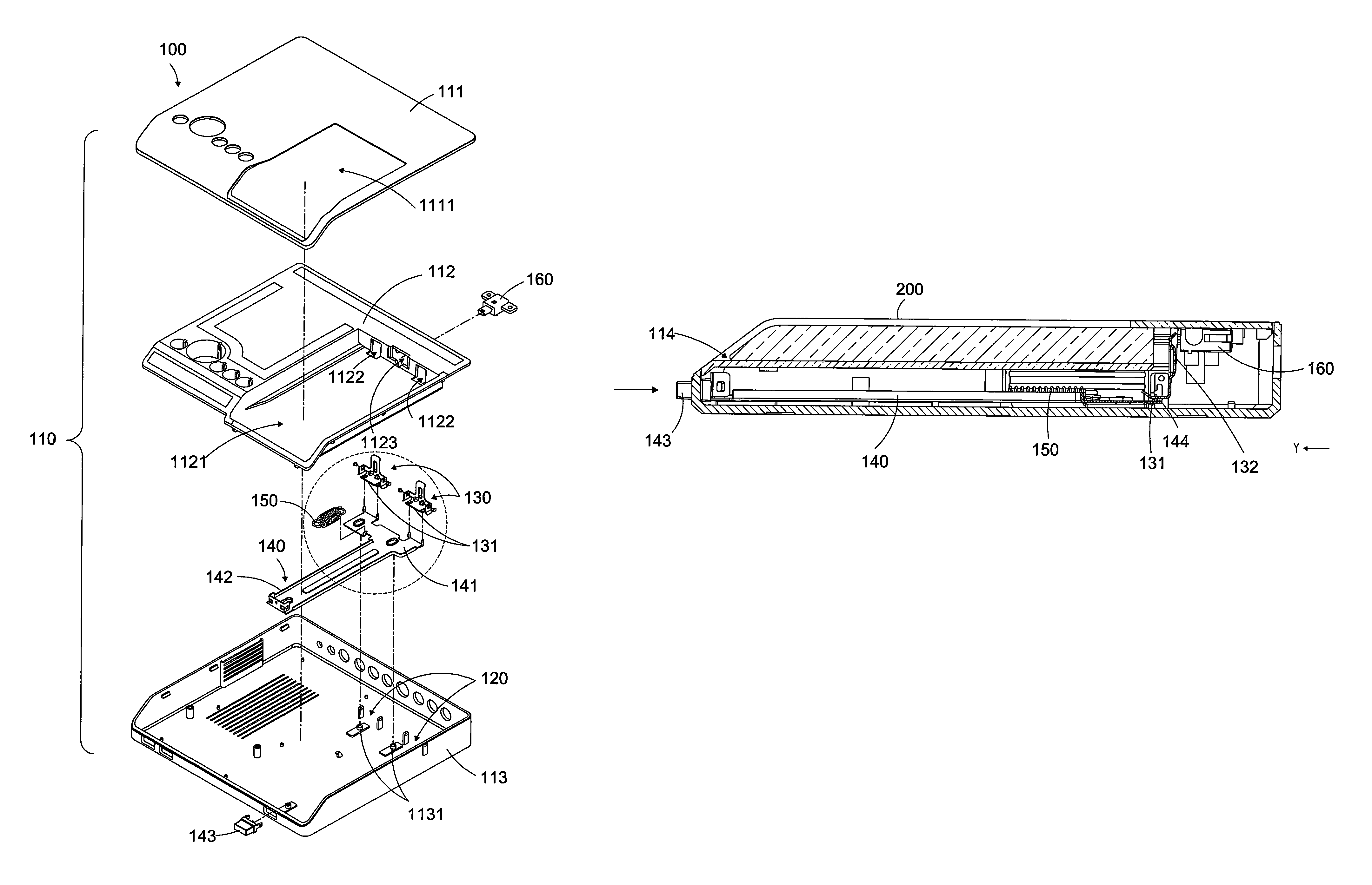
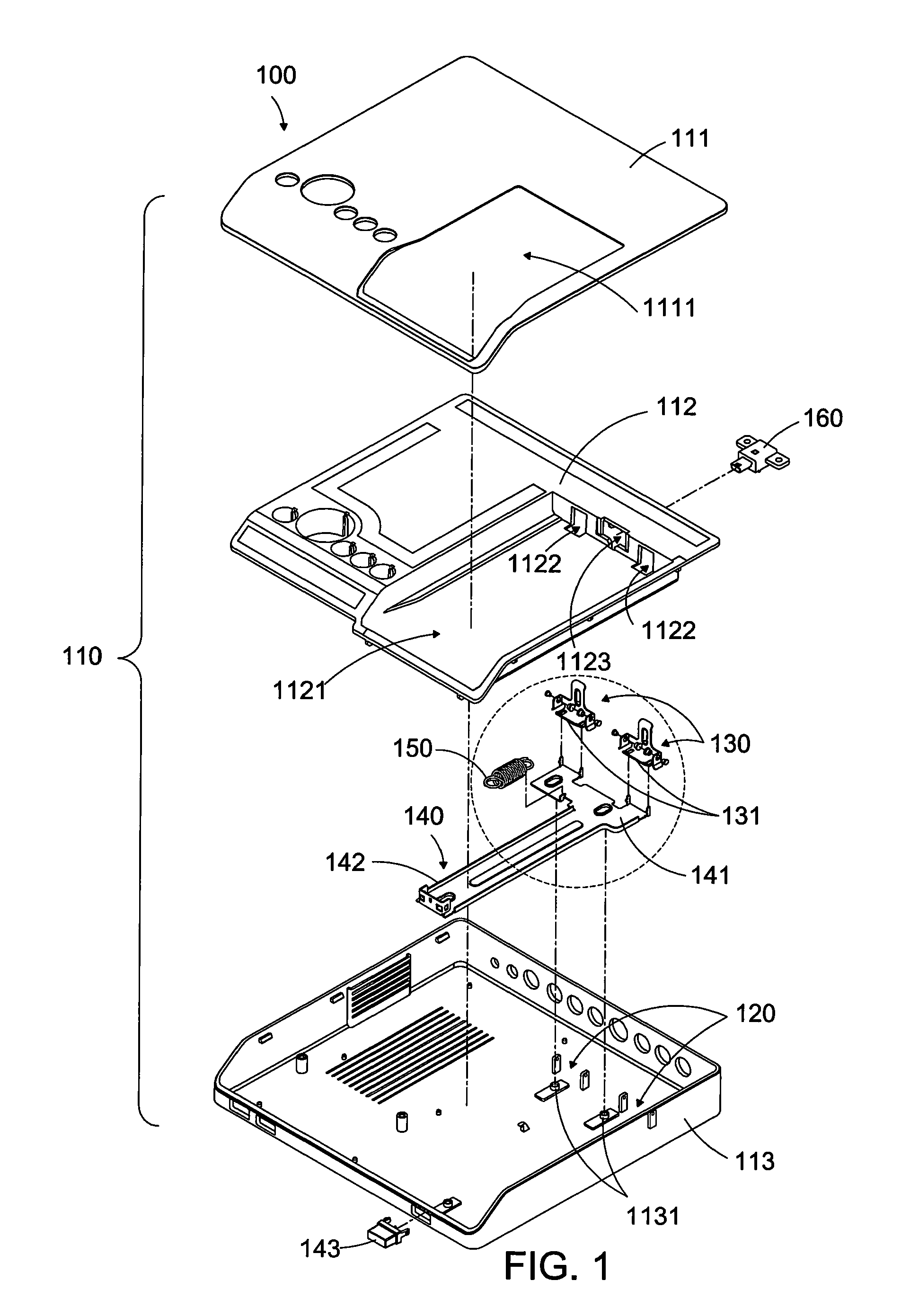
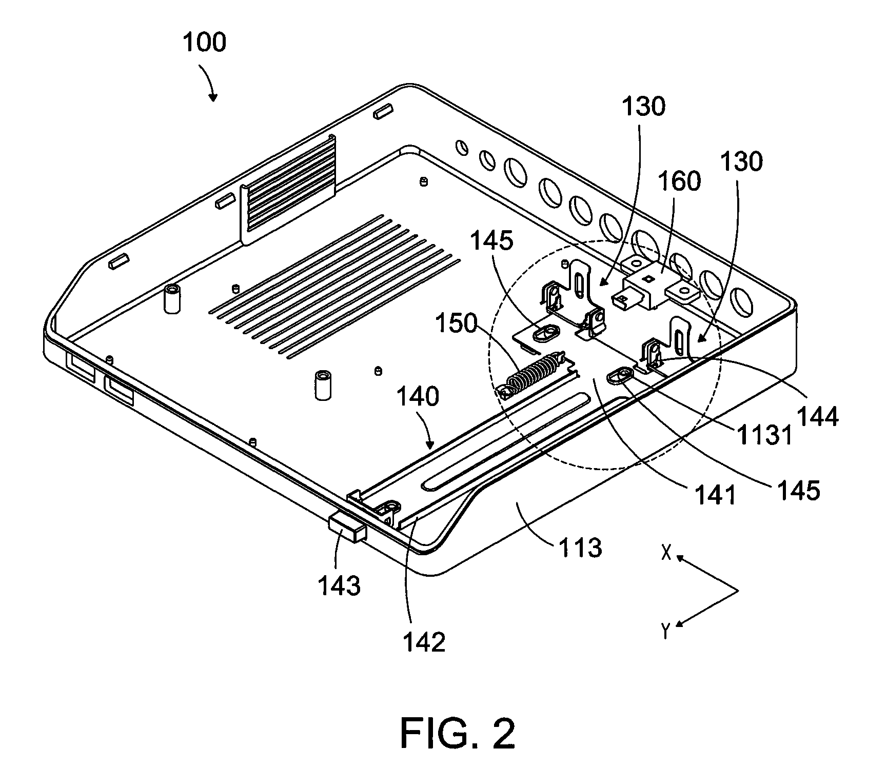
[0022]Referring to FIGS. 1, 2, 3, and 4, an electronic device case structure 100 having function of ejecting a peripheral device 200 inserted therein according to an embodiment of the present invention is shown. The electronic device case structure 100 is applicable to an electronic device equipped with the peripheral device 200, and the peripheral device 200 can be easily ejected from the electronic device case structure 100.

[0023]Referring to FIGS. 1 and 2, the electronic device case structure 100 includes a case body 110, one or more pivoting seats 120, one or more pushing members 130, a driving member 140, and an elastic member 150.

[0024]Referring to FIGS. 1 and 3, the case body 110 includes an upper cover 111, a middle cover 112, and a lower cover 113. The middle cover 112 is combined with the lower cover 113, such that an accommodating space is defined inside the case body 110. The upper cover 111 is further combined with the middle cover 112, so as to cover uneven structure o...


PUM


Abstract

An electronic device case structure includes a case body, a pivoting seat, a pushing member, and a driving member. An accommodating slot is formed on the case body for a peripheral device to be inserted therein. The case body has a disposition hole communicating with the accommodating slot and an internal space of the case body. The pivoting seat is disposed in the case body, and the pushing member is pivoted to the pivoting seat. The pushing member has a pushing segment, protruding in the accommodating slot through the disposition hole and a connecting segment. The driving member includes a coupling end connected to the connecting segment and an operation end, The operation end is to be pressed to make the driving member move inwards, so as to have the pushing segment to move towards the outside of the accommodating slot, thereby pushing and ejecting the peripheral device.

Description

CROSS-REFERENCES TO RELATED APPLICATIONS[0001]This non-provisional application claims priority under 35 U.S.C. §119(a) on Patent Application No. 98210308 filed in Taiwan, R.O.C. on 2009 / 6 / 10, the entire contents of which are hereby incorporated by reference.BACKGROUND OF THE INVENTION[0002]1. Technical Field[0003]The present invention relates to installing a removable peripheral device to a electronic device and removing the removable peripheral device from the electronic device, and more particularly to an electronic device case structure having an ejecting mechanism.[0004]2. Related Art[0005]Functions of an electronic device can be changed or expanded by installing and removing a removable peripheral device. For example, for a multimedia electronic device, a storage capacity is expanded and the storage content is directly replaced through replacing a removable hard disk. For ease of removal, the hard disk is usually installed in a tray, and a case of a multimedia computer device i...

Claims


Application Information

Patent Timeline
Patent Type & Authority Patents(United States)
IPC IPC(8): H01R13/62
CPCG11B33/124
Inventor HUANG, YU-HSINLEE, YU-CHENCHOU, CHUN-YI
Owner WISTRON CORP
Why Eureka
Try Eureka