Fitting ring for an opening roller of an open-end spinning device

a technology of opening roller and fitting ring, which is applied in the direction of open-end spinning machines, drafting machines, textiles and paper, etc., can solve the problems of ineffective needle roller rings, and inability to achieve needle roller rings in practi

Inactive Publication Date: 2010-08-24
SAURER GERMANY GMBH & CO KG
View PDF16 Cites 0 Cited by
  • Summary
  • Abstract
  • Description
  • Claims
  • Application Information

AI Technical Summary

Benefits of technology

[0015]Proceeding from the aforementioned prior art, the invention is based on the object of providing clothing rings which allow a uniform, gentle combing out of the fibers from a feed fiber band. In addition, the clothing rings according to the invention should ensure proper transportation of the combed-out individual fibers within the opening roller housing and their reliable transfer to a fiber guide channel.
[0018]The configuration of a clothing ring according to the invention, in which the axial separation spacing of the teeth predetermined by the peripheral groove is significantly smaller than the height of the teeth and the teeth have tooth flanks, which are continuously concavely curved into the groove, has the advantage that no edges or the like which, on the one hand, damage the fibers and, on the other hand, impair the transportation flow within the opening roller housing, are present in the region of the tooth flanks, via which, as is known, a large part of the opening and transportation work of the fibers takes place.
[0019]In other words, by avoiding a bend edge between the tooth flanks and the side walls, a gentle and uniform opening of the individual fibers is achieved, in particular in sensitive synthetic yarns.
[0020]An embodiment in which the curvature of the tooth flanks continuously becomes smaller toward the tip of the tooth proceeding from the base of the groove respectively arranged between two teeth, has proven to be particularly advantageous with regard to gentle fiber band opening of sensitive yarns. A clothing ring configured in this manner does not only comb the individual fibers particularly gently from the feed fiber band, but also leads to a very uniform transporting air flow circulating between the tooth flanks and the side walls.
[0022]As corresponding measurements have shown, clothing rings which have the above-described tooth shape, in particular in synthetic material, lead to yarns with improved yarn-dynamic test values. In other words, the yarns produced with the clothing rings according to the invention, compared to yarns which have been produced with known clothing rings, have a higher yarn strength.

Problems solved by technology

Clothing rings of this type equipped with individual needles, which are described, for example, in U.S. Pat. No. 4,798,046, have not proven successful, however.
In other words, although the most varied forms of needles were tested, as described in U.S. Pat. No. 4,798,046, these needle roller rings did not succeed in practice.
Solid rings with a configuration as described in German Patent Publication DE-OS 1 939 683 were, however, not able to be successful on the market as the transporting behavior of these clothing rings proved to be inadequate, above all, because of the relatively small tooth height.
A bend edge of this type has a disadvantageous effect on the combing out behavior of the clothing ring.
In other words, the fiber separation during the fiber band opening is to some extent inadequate, or inadequately uniform, in these known clothing rings.

Method used


Image

  • Fitting ring for an opening roller of an open-end spinning device
  • Fitting ring for an opening roller of an open-end spinning device
  • Fitting ring for an opening roller of an open-end spinning device

Examples


Embodiment Construction

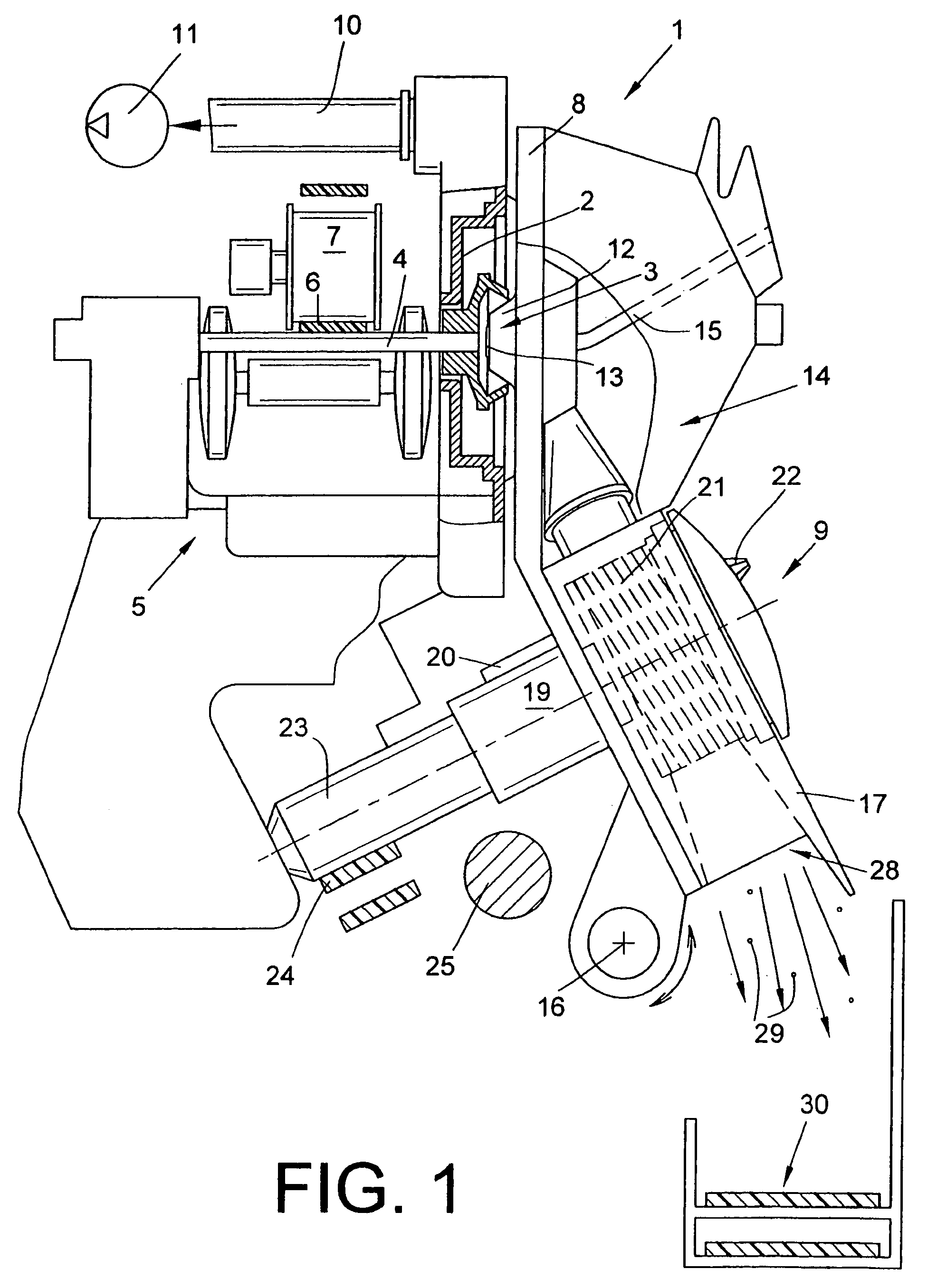
[0032]The open-end rotor spinning device 1 shown in FIG. 1 has, as known, a rotor housing 2 in which a spinning rotor 3 revolves at a high rotational speed. The spinning rotor 3 is in this case supported by its rotor shaft 4 in the interspace of a support disc mounting 5 and is acted upon by a tangential belt 6 along the length of the machine, which belt is set by a pressure roller 7. The rotor housing 2, which is open at the front per se, is closed during operation by a pivotably mounted cover element 8. The rotor housing 2 is also connected by means of a corresponding pneumatic line 10 to a negative pressure source 11, which produces the negative spinning pressure necessary in the rotor housing 2. A so-called channel plate adaptor 12 which has a yarn draw-off nozzle 13 and the opening region of a fiber guide channel 14, is arranged in a receiving opening, not shown in more detail, of the cover element 8. A yarn draw-off tube 15 adjoins the yarn draw-off nozzle 13 here.

[0033]A fibe...


PUM

PropertyMeasurementUnit
angleaaaaaaaaaa
angleaaaaaaaaaa
angleaaaaaaaaaa

Abstract

Clothing ring (27) for an opening roller (21) of an open-end spinning device (1), comprising teeth (38) which are formed by at least one groove (39) incorporated in the peripheral face of a basic body (45) and running in the peripheral direction, and a plurality of indents (40) arranged substantially in the axial direction. An axial separation spacing (t) of the teeth (38) is predetermined by the groove (39) and is significantly smaller than the height (H) of the teeth (38). The teeth (38) have tooth flanks (42) which are continuously concavely curved into the groove (39).

Description

CROSS-REFERENCES TO RELATED APPLICATIONS[0001]This application claims the benefit of German patent application 10 2006 005 693.0, filed Feb. 8, 2006, herein incorporated by reference.BACKGROUND OF THE INVENTION[0002]The invention relates to a clothing ring for an opening roller of an open-end spinning device.[0003]Clothing rings for the opening rollers of open-end spinning devices have been known for a long time in various embodiments and described in numerous patent documents. Opening rollers of this type are used, in particular, to open a fiber band (commonly referred to as a sliver) supplied in spinning cans to the workstations of an open-end spinning machine into individual fibers before being fed into a spinning means, revolving at a high rotational speed, of the open-end spinning device. Opening rollers of this type rotating at a high rotational speed, for this purpose, have on their periphery, a tearing structure which combs the fiber band supplied and in the process opens it...

Claims


Application Information

Patent Timeline
Patent Type & Authority Patents(United States)
IPC IPC(8): D01H4/30
CPCD01H4/32
Inventor WASSENHOVEN, HEINZ-GEORGMEIER, WOLFGANGWINZEN, LOTHARRIEDE, BRIGITTE
Owner SAURER GERMANY GMBH & CO KG
Why Eureka
Try Eureka