Transporting System, Image Forming System, and Controller

a technology of image forming system and transport system, which is applied in the direction of transportation and packaging, other domestic articles, synthetic resin layered products, etc., can solve the problems of difficult to carry out high-precision control of tension, slippage between the rollers and the sheet, and difficulty in carrying out controls properly, so as to suppress the degradation of image quality and improve the quality of images formed on the sh

Active Publication Date: 2014-10-02
BROTHER KOGYO KK
View PDF5 Cites 9 Cited by
  • Summary
  • Abstract
  • Description
  • Claims
  • Application Information

AI Technical Summary

Benefits of technology

[0010]The present teaching is made in view of such problems, and an object thereof is to provide a technique capable of controlling the state quantity and tension of a sheet with high precision in a system transporting the sheet with a plurality of rollers.
[0028]According to the present teaching, by using the sum of, and the difference between, the control inputs U1 and U2, to control the first driving device and the second driving device, it is possible to control the state quantity and tension of the sheet with high precision in transport of the sheet with the two rollers. As a result, according to the present teaching, it is possible to construct the transporting system with high performance.
[0045]When ink droplets are jetted from a jetting portion of the image forming device to form images on the sheet, if the tension of the sheet cannot be controlled, then a change in flexure of the sheet may cause a deviation in the landing points of the ink droplets, and thereby the quality of the images formed on the sheet may be deteriorated. In contrast to this, according to the image forming system of the present teaching, because the sheet can be transported with an appropriate tension, it is possible to suppress the degradation in image quality caused by the flexure.

Problems solved by technology

However, in the conventional techniques, although the driving control for adjusting the sheet speed is carried out for a plurality of rollers, the driving control for adjusting the sheet tension is carried out only for the send-out roller among the plurality of rollers.
Therefore, there is a problem that it is difficult to carry out a high-precision control of the tension.
Especially, in a system transporting a short sheet such as a paper sheet of a standard size, etc., if the sheet is subjected to an excessive load, then slippage will occur between the rollers and the sheet.
Hence, it is difficult to carry out the controls properly by conventional way which controls the sheet tension with only one roller while controlling a state quantity of the sheet (position, speed, acceleration, or the like.).

Method used


Image

  • Transporting System, Image Forming System, and Controller
  • Transporting System, Image Forming System, and Controller
  • Transporting System, Image Forming System, and Controller

Examples


Embodiment Construction

[0061]Hereinbelow, referring to the accompanying drawings, an embodiment of the present teaching will be explained.

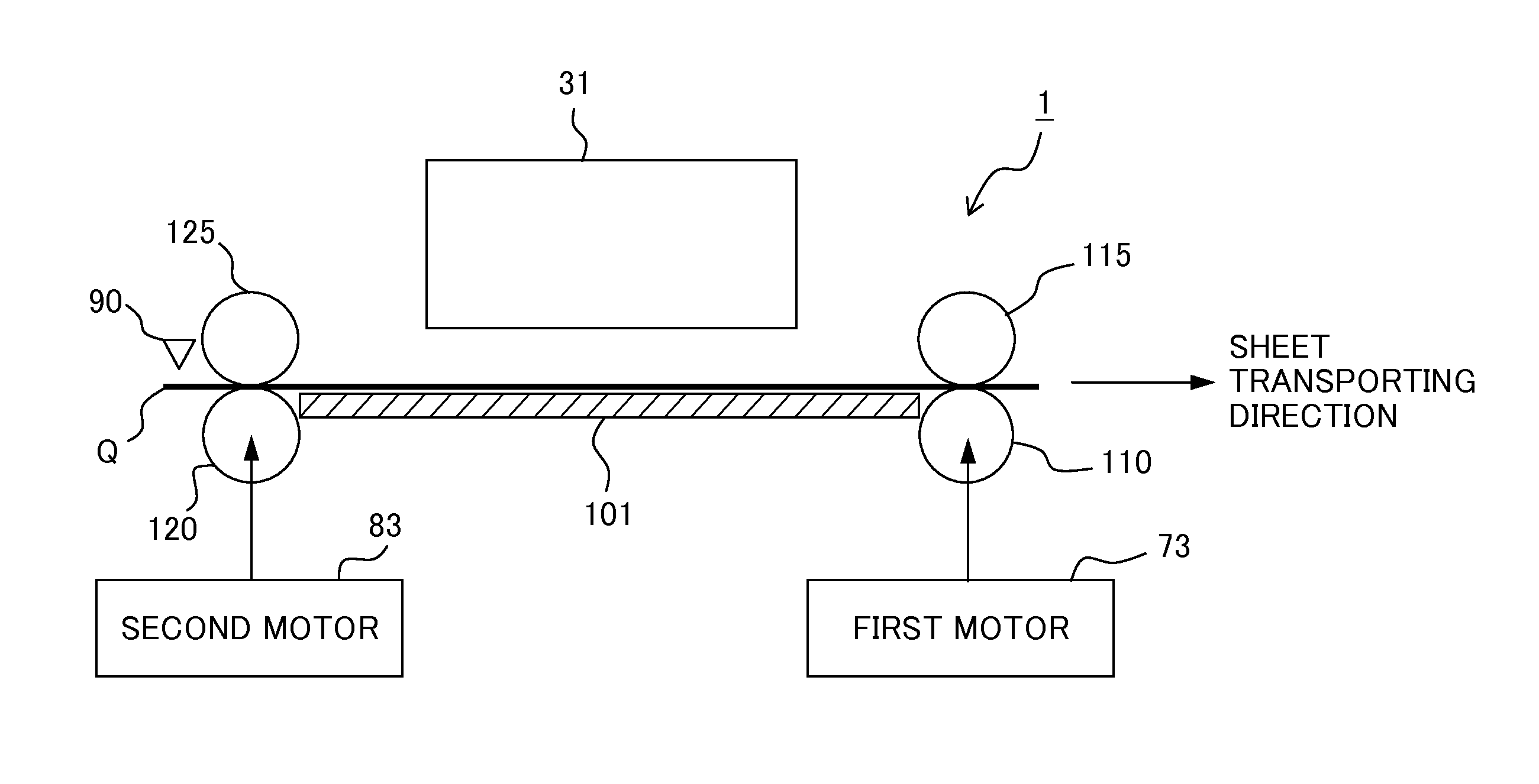
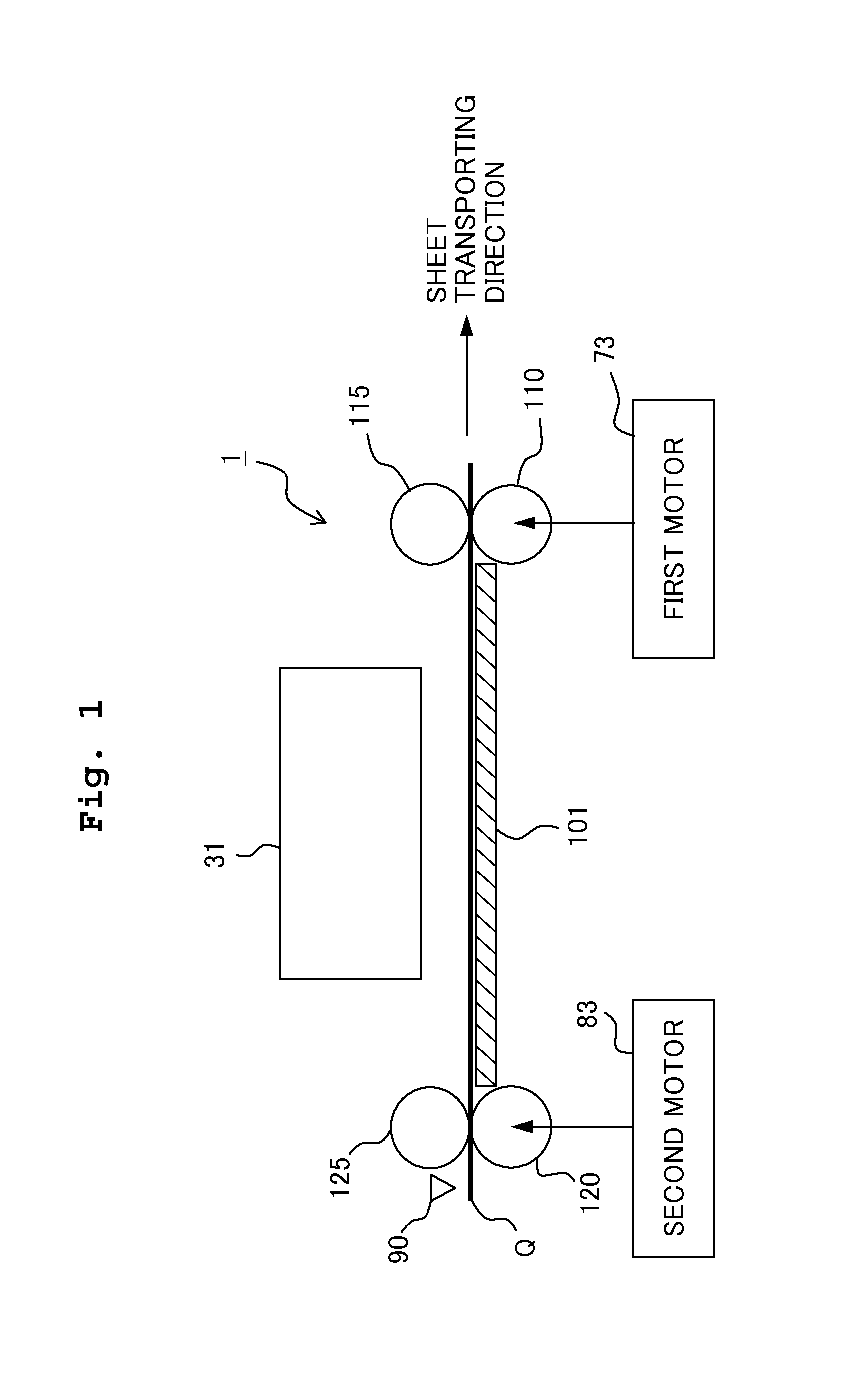
[0062]An image forming system 1 of this embodiment is formed as an ink jet printer. As shown in FIG. 1, this image forming system 1 includes an ink jet head 31 positioned above a platen 101 constituting a transporting path for the sheet Q. The ink jet head 31 includes a nozzle group (not shown) on the lower surface to jet ink droplets toward the sheet Q passing through over the platen 101. By this jetting operation, the ink jet head 31 forms images on the sheet Q.

[0063]The ink jet head 31 has such a shape as elongated in a line direction (the normal direction of FIG. 1, that is, the direction perpendicular to the page of FIG. 1), and has such a configuration as capable of forming images simultaneously in the line direction on the entire area of the sheet Q passing through over the platen 101.

[0064]A currently widespread ink jet printer forms an image in the line directi...


PUM

PropertyMeasurementUnit
reaction forceaaaaaaaaaa
tensionaaaaaaaaaa
rotation speedaaaaaaaaaa

Abstract

There is provided a transporting system including two rollers to transport a sheet, two driving devices to drive the rollers, two measuring devices to measure state quantities Z1 and Z2 concerning the rollers, and a controller to control the transport. The controller includes first and second estimating units to estimate values R1 and R2 related to reaction forces act on the rollers, a first calculating unit to calculate control input U1 in accordance with a deviation between a target state quantity and (Z1+Z2) / 2, a second calculating unit to calculate control input U2 in accordance with a deviation between a target value and (R1−R2) / 2, a first drive controller to input a control signal in accordance with (U1+U2) to the first driving device, and a second drive controller to input a control signal in accordance with (U1−U2) to the second driving device.

Description

CROSS REFERENCE TO RELATED APPLICATION[0001]The present application claims priority from Japanese Patent Application No. 2013-072750, filed on Mar. 29, 2013, the disclosure of which is incorporated herein by reference in its entirety.BACKGROUND OF THE INVENTION[0002]1. Field of the Invention[0003]The present invention relates to transporting systems for transporting sheets, image forming systems, and controllers.[0004]2. Description of the Related Art[0005]Conventionally, as transporting systems for transporting sheets, there have been known systems with a plurality of rollers provided along a sheet transporting path.[0006]Further, also as transporting systems, there have been known systems which send out sheets, which are convolved into rolls, to the downstream side of the transporting path. For example, there is known such a system which includes a send-out roller provided to send out a sheet convolved into a roll, and a transporting roller provided on the downstream side from the...

Claims


Application Information

Patent Timeline
Patent Type & Authority Applications(United States)
IPC IPC(8): B65H7/20B65H7/06B65H5/06
CPCB65H7/20B65H5/06B65H7/06B41J13/0027B65H5/062B65H2301/4474B65H2404/143B65H2515/31B65H2515/32B65H2553/51B65H2220/09Y10T428/31544Y10T428/3154B65H2220/03B65H2220/02B65H2220/01B32B27/08B32B27/322B32B27/34B32B2457/08H05K1/036
Inventor IESAKI, KENICHI
Owner BROTHER KOGYO KK
Why Eureka
Try Eureka