Transportation roller, transportation unit, printing apparatus, and method of manufacturing transportation roller

Inactive Publication Date: 2011-06-16
SEIKO EPSON CORP
View PDF27 Cites 8 Cited by
  • Summary
  • Abstract
  • Description
  • Claims
  • Application Information

AI Technical Summary

Benefits of technology

[0025]By adopting such a method, the cylindrical shaft having a predetermined thickness is formed by a pressing process, and then the outer peripheral surface on the side corresponding to the joint portion of the cylindrical shaft is cut by a predetermined thickness. Accordingly, the outer diameter shape of the cylindrical shaft is changed from the cylindrical shape, but the inner diameter shape of the cylindrical shaft is maintained in the circular shape. Then, when the cylindrical shaft is subjected to the centerless grinding process, the o

Problems solved by technology

Meanwhile, since the solid member causes an increase in the weight and cost, a method of decreasing the weight and the cost has been examined.
However, even when the cylindrical shaft has excellent linearity at the manufacturing stage, warpage may occur

Method used


Image

  • Transportation roller, transportation unit, printing apparatus, and method of manufacturing transportation roller
  • Transportation roller, transportation unit, printing apparatus, and method of manufacturing transportation roller
  • Transportation roller, transportation unit, printing apparatus, and method of manufacturing transportation roller

Examples


Embodiment Construction

[0053]Hereinafter, exemplary embodiments of the invention will be described with reference to the accompanying drawings.

[0054]Further, in the drawings which will be used for the following description, the scales of the respective members are appropriately changed so that the respective members have recognizable sizes.

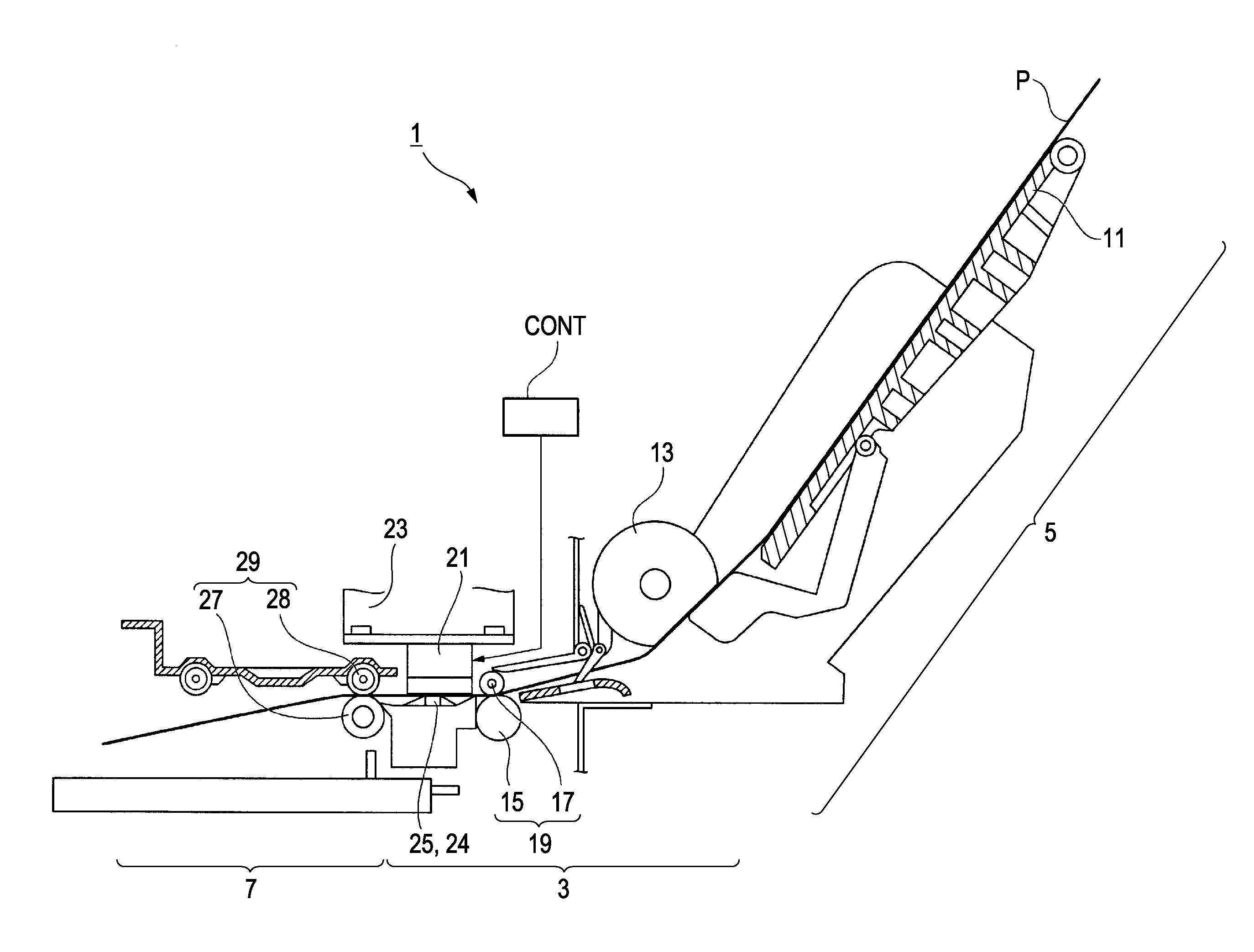
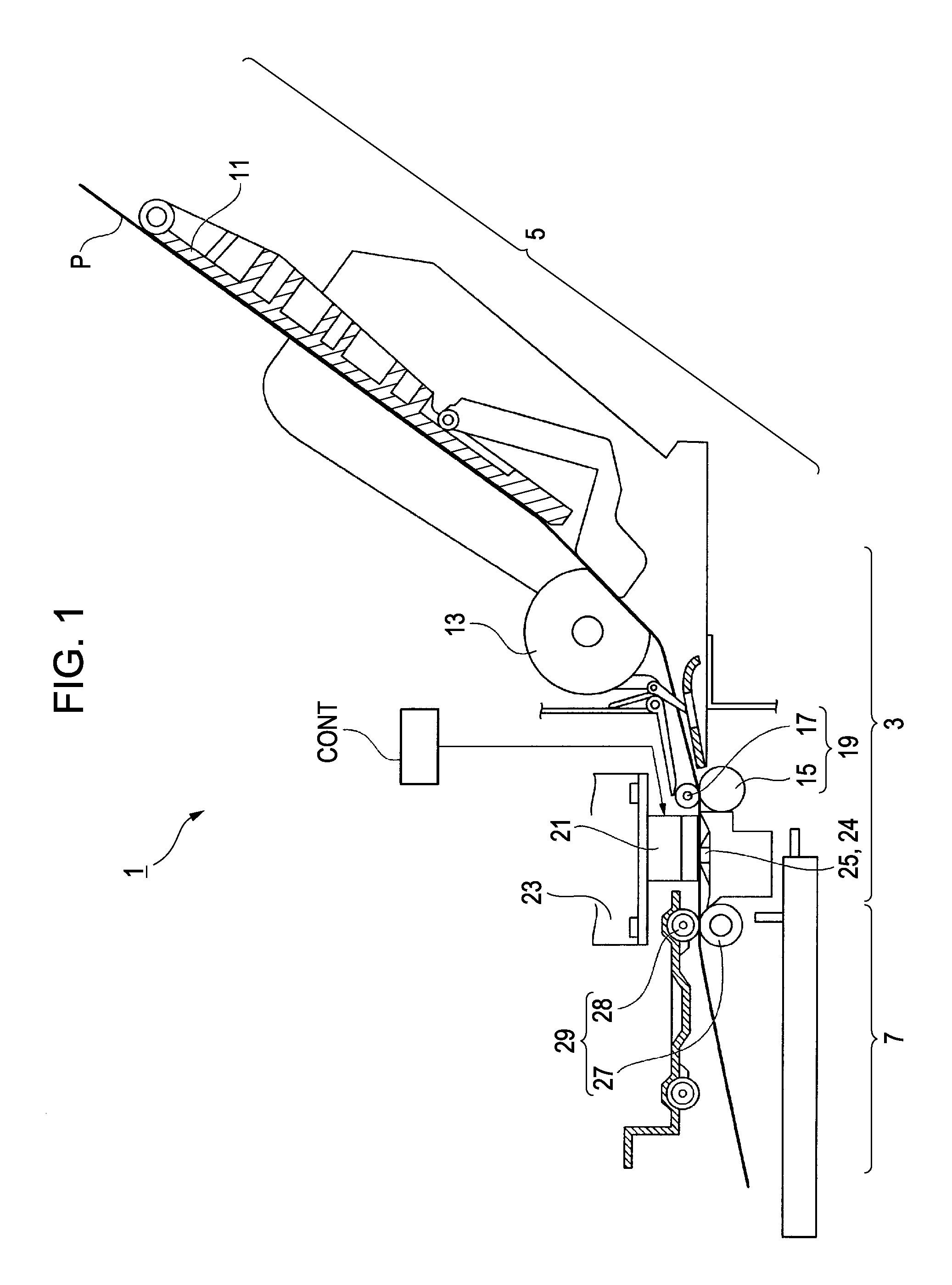
[0055]FIG. 1 is a side cross-sectional view illustrating an ink jet printer according to the embodiment of the invention.

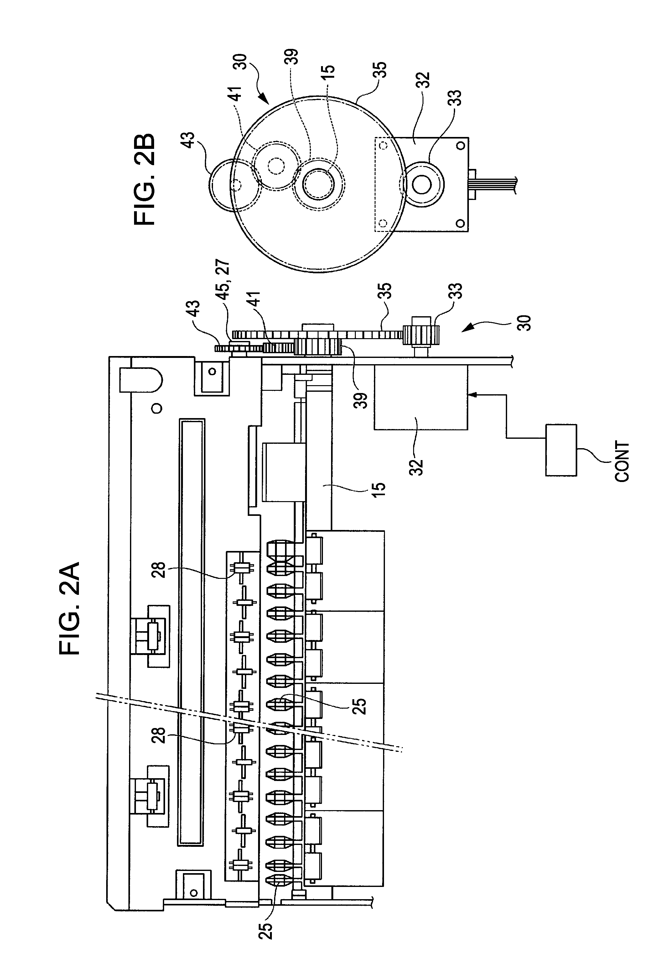
[0056]FIG. 2A is a plan view illustrating a transportation roller mechanism of the ink jet printer, and

[0057]FIG. 2B is a side view illustrating a driving system of the transportation roller mechanism.

[0058]As shown in FIG. 1, an ink jet printer (printing apparatus) 1 includes a printer body 3; a sheet feeding unit 5 which is provided in the rear upper portion of the printer body 3; and a sheet discharging unit 7 which is provided in front of the printer body 3.

[0059]A sheet feeding tray 11 is provided in the sheet feeding unit 5, and a plurality of s...


PUM


Abstract

Provided is a transportation roller, a transportation unit, a printing apparatus, and a method of manufacturing a transportation roller capable of reducing warpage with the elapsing of time. A transportation roller includes: a roller body which is formed in a cylindrical shape by subjecting a metal sheet to a pressing process and allowing a pair of end portions thereof to face each other, and has a joint formed between the pair of end portions, wherein in a sectional shape perpendicular to the axis of the roller body, a thickness of a joint facing portion facing the joint with the axis interposed therebetween is larger than a thickness of a joint portion provided with the joint, and a thickness of the roller body connecting the joint facing portion and the joint portion is gradually changed as it goes from the joint facing portion to the joint portion.

Description

CROSS-REFERENCE TO RELATED APPLICATIONS[0001]This application claims the benefit of priority to Japanese Patent Application No. 2009-284878 filed Dec. 16, 2009, the contents of which are hereby incorporated by reference in their entirety.BACKGROUND[0002]1. Technical Field[0003]The present invention relates to a transportation roller, a transportation unit, a printing apparatus, and a method of manufacturing a transportation roller.[0004]2. Related Art[0005]For some time, a printing apparatus for printing information on a sheet-like printing medium has been used, and the printing apparatus includes a transportation unit that transports the printing medium as a transportation target. The transportation unit includes a transportation roller that is used to transport the printing medium. A solid round bar member is generally used as the transportation roller. The printing medium is held by the transportation roller, and is transported when the transportation roller is rotated. In additi...

Claims


Application Information

Patent Timeline
IPC IPC(8): B41J13/02F16C13/00B21K21/00
CPCF16C13/00
Inventor SAITO, KOICHISHINTATE, TORUOKUYAMA, SHINJIOZAWA, KENJI
Owner SEIKO EPSON CORP
Why Eureka
Try Eureka