Chopper and slicer

a technology which is applied in the field of chopper and slicer, can solve the problems of increasing cost and complexity, and the device is more difficult to clean,

Inactive Publication Date: 2010-08-24
PROGRESSIVE INT
View PDF77 Cites 22 Cited by
  • Summary
  • Abstract
  • Description
  • Claims
  • Application Information

AI Technical Summary

Problems solved by technology

In other examples, complicated levers, springs, or gears are involved and these components increase cost and complexity as well as make the device more difficult to clean.

Method used


Image

  • Chopper and slicer
  • Chopper and slicer
  • Chopper and slicer

Examples


Embodiment Construction

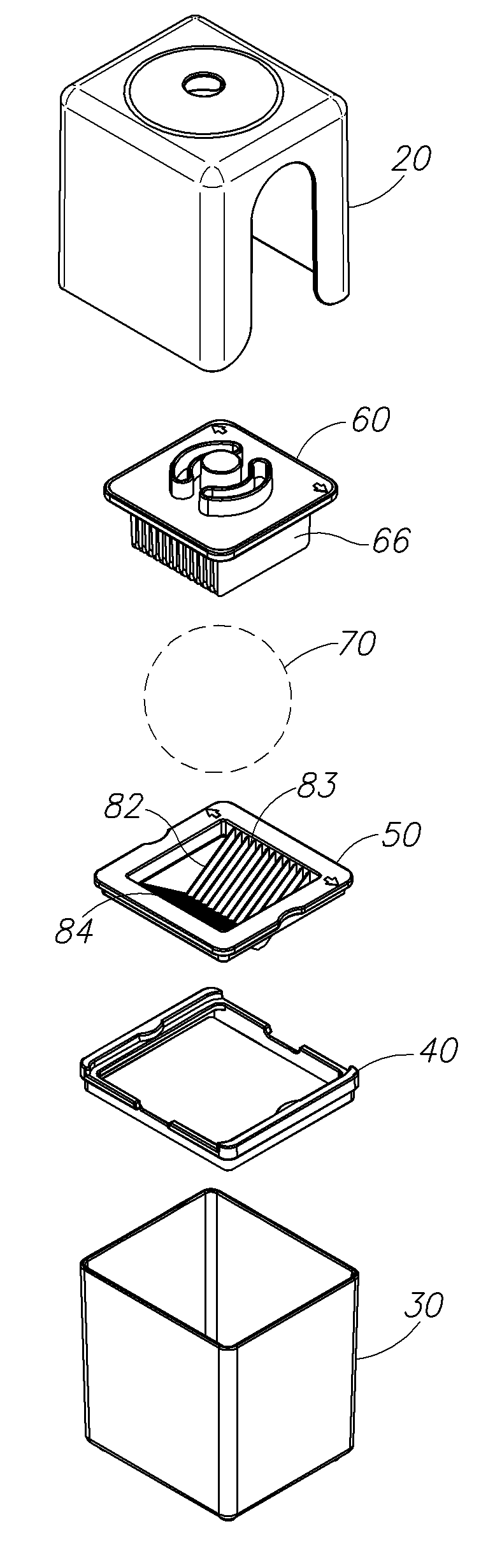
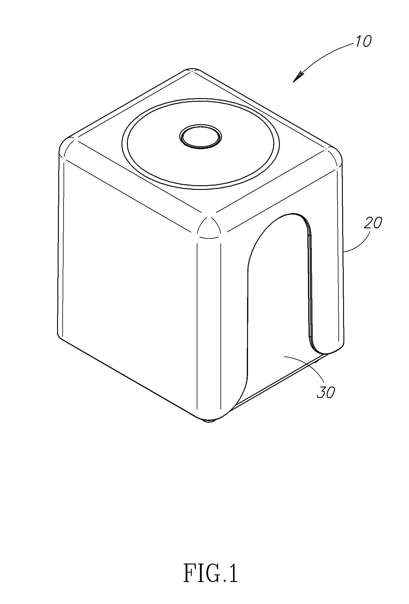
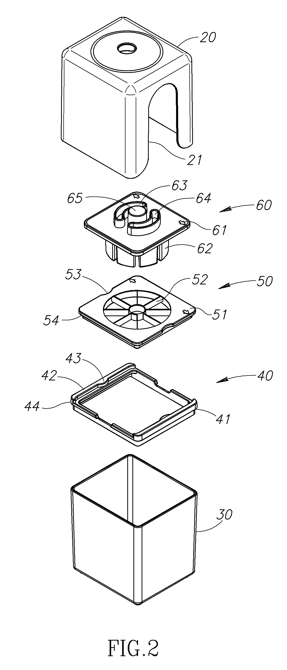
[0016]FIG. 1 shows a perspective view of a preferred slicing device 10. As shown, an outer pusher housing 20 surrounds a container 30. In this example of the invention, the container 10 is generally of a rectangular cubic shape, having a base, upwardly extending sidewalls, and an open top (best seen in FIG. 2). The pusher housing 20 is of a mating, complementary shape in that an interior surface of the housing snugly receives an exterior surface of the container so that the housing is able to slide up and down about the container. As shown, the interior of the sidewalls of the housing abut the majority of the exterior of the container and forms a close fit, thereby frictionally engaging the container as the housing slides up and down. In this version the housing and container are not permanently fastened to one another, but rather can be freely separated if the housing is pulled upward from the container a sufficient distance.

[0017]In other versions of the invention, other shapes fo...


PUM

PropertyMeasurementUnit
shapeaaaaaaaaaa
distanceaaaaaaaaaa
shapesaaaaaaaaaa

Abstract

A food chopper and slicer includes a lower receptacle for holding chopped food items and one or more blades at the top. A pushing element is secured within an outer housing, with the outer housing being configured to snugly and slideably fit around the receptacle. The housing forms a guide path such that the pushing element follows a generally straight and vertical path as it moves downward toward the blades.

Description

PRIORITY CLAIM[0001]This application claims the benefit of prior U.S. Provisional Application Ser. No. 61 / 042,648, filed Apr. 4, 2008.FIELD OF THE INVENTION[0002]This invention relates generally to food slicing devices, particularly including devices in which a food item is sliced by urging it through a grid of slicing blades.BACKGROUND OF THE INVENTION[0003]There are a variety of slicing devices on the market in which a food item such as an onion is sliced by urging it through a tray or grid of slicing blades. In some examples of such devices, a pusher and slicing grid are pivotally movable with respect to one another and brought together to slice the item. In other examples, complicated levers, springs, or gears are involved and these components increase cost and complexity as well as make the device more difficult to clean.SUMMARY OF THE INVENTION[0004]A preferred example of the invention includes a lower receptacle for holding chopped food items and one or more blades at a top o...

Claims


Application Information

Patent Timeline
Patent Type & Authority Patents(United States)
IPC IPC(8): A47J17/00
CPCB26D3/26A47J43/25B26D1/0006B26D1/553Y10S83/932B26D2001/0033B26D2001/006B26D3/24Y10T83/9498Y10T83/95
Inventor PETERSON, SARAH S.KAPOSI, SASCHA
Owner PROGRESSIVE INT
Why Eureka
Try Eureka