Square baler with an ejector system

Active Publication Date: 2010-08-24
BLUE LEAF I P INC
View PDF4 Cites 15 Cited by
  • Summary
  • Abstract
  • Description
  • Claims
  • Application Information

AI Technical Summary

Benefits of technology

[0011]A potential advantage of the present invention is that the dogs do not need to be controlled, i.e. selectively enabled and disabled. In the preferred embodiment of the invention, each dog is pivotably mounted on the shuttle assembly and designed to act in a manner analogous to the pawl of a pawl and ratchet. Thus, each dog will pivot into an extended gripping position during the forward movements of the shuttle to advance the bale towards the discharge outlet and will retract during reverse movements of the shuttle assembly to slip relative to the bale.
[0012]When using pivotable dogs, they may be biased into their extended position by gravity or by means of a spring. Alternatively, the dogs may be designed to protrude slightly into the bale case when retracted so that they will be raised automatically into their extended position as they grip into a bale.

Problems solved by technology

Apart from the complexity resulting from the need to control dogs individually, the existing ejector systems suffer from the disadvantage that the operator needs first to inspect the position of the bales in the bale case in order to decide on which of the dogs to activate.

Method used


Image

  • Square baler with an ejector system
  • Square baler with an ejector system

Examples


Embodiment Construction

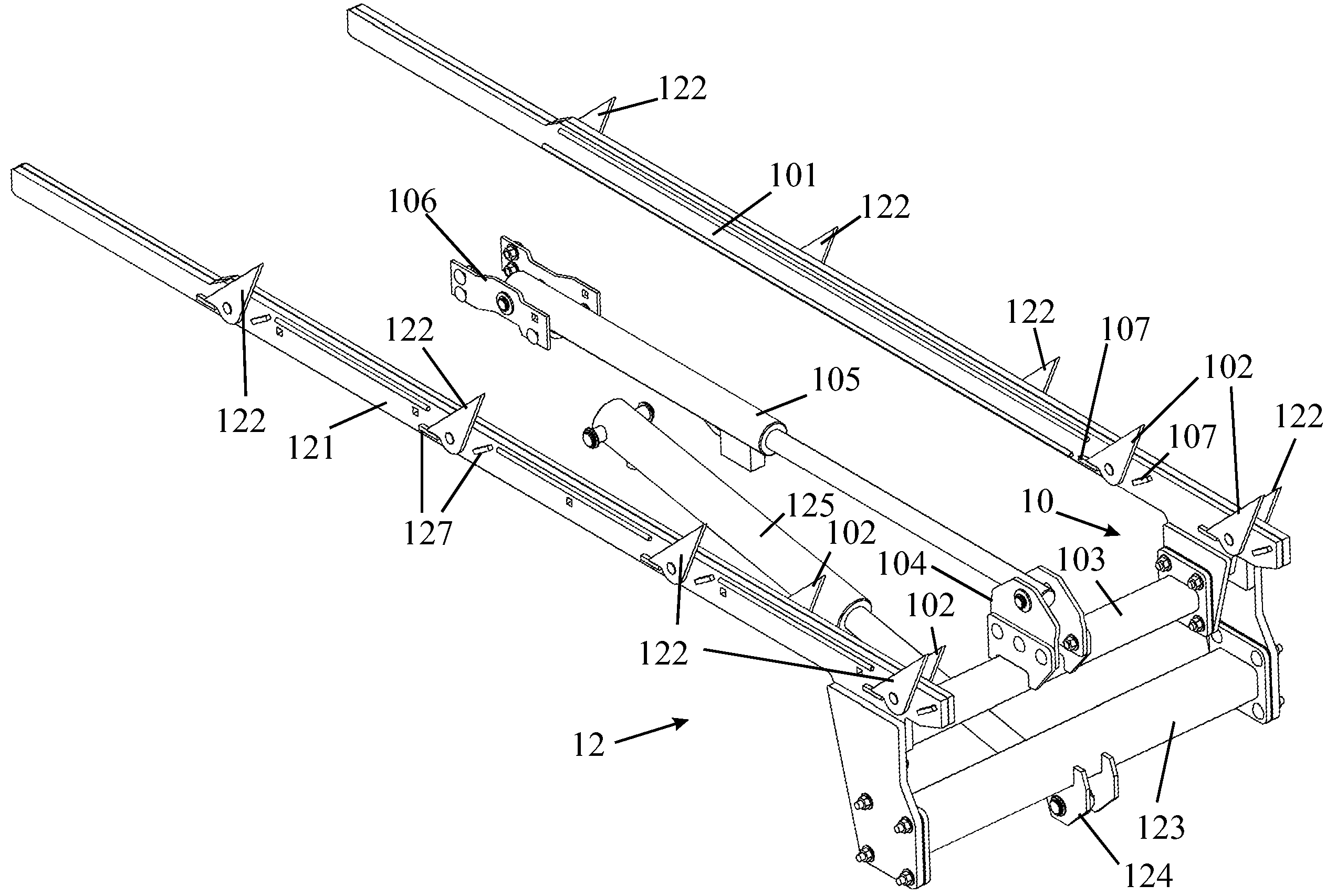
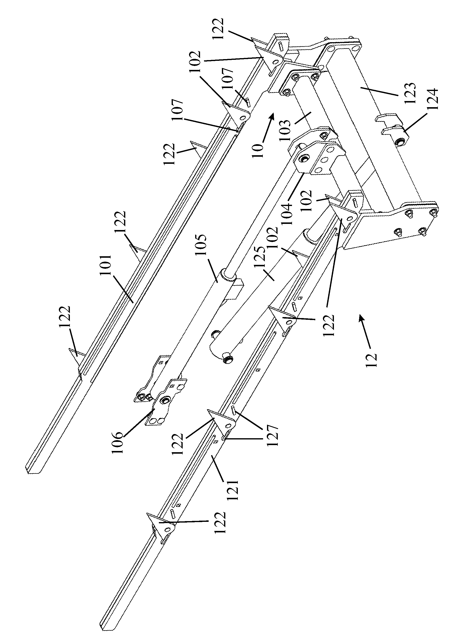
[0015]The integration of an ejector system into a square baler is well documented in the prior art discussed above, having several drawings depicting the manner in which that ejector system is mounted in the baler. In the interest of simplicity, the following description will concentrate on the construction of the ejector system and will only describe the bale case to the extent necessary for an understanding of the invention.

[0016]To ensure that it has sufficient rigidity, the floor of the bale case is not formed as a continuous flat surface. The floor can be formed of sheet metal that is bent to provide longitudinally extending channels or it can be formed of separate square section tubes that are welded to cross bars at their ends leaving open grooves between the individual tubes. The shuttle assemblies of ejector systems are designed to sit in such longitudinal grooves, channels or open rails with only their dogs capable of extending upwards above the floor surface on which the ...


PUM


Abstract

A square baler has an ejector system including a shuttle assembly mounted in a wall of the bale case for reciprocation parallel to the direction of movement of the bales in the bale case. A least one dog mounted on the shuttle assembly engages in the last bale in the bale case positioned nearest the discharge outlet and advances the bale incrementally in response to reciprocation of the shuttle assembly. A second shuttle assembly is mounted in a wall of the bale case for reciprocation independently of the first shuttle assembly. The second shuttle assembly has at least one dog to engage in the next-to-last bale in the bale case. By selecting which of the shuttle assemblies to activate, an operator may elect to eject only the last base in the bale case or the last two bales.

Description

FIELD OF THE INVENTION[0001]The present invention relates a square baler having an ejector system.BACKGROUND OF THE INVENTION[0002]U.S. Pat. No. 5,540,144, which is believed to represent the closest prior art to the present invention, shows a square baler which, instead of using the compacting plunger to unload tied bales from the bale case, comprises an auxiliary ejector system to enable the operator to off-load completed bales. The ejector system comprises a shuttle assembly housed within hollow rails of the bale case. The shuttle assembly consists of a frame that is reciprocated in the direction of movement of the compacting plunger and has dogs projecting upwards from it to engage in the underside of the bales. The dogs grip the bale only during the forward stroke of the shuttle assembly, when it is moving towards the discharge outlet of the bale case, and slip relative to the underside of the bale during the return stroke. In this way, the reciprocation of the shuttle assembly ...

Claims


Application Information

Patent Timeline
Patent Type & Authority Patents(United States)
IPC IPC(8): B30B9/30B30B15/32
CPCA01F15/0875
Inventor DE RYCKE, STEFANNAAKTGEBOREN, ADRIANUSBIEBUYCK, RONALD
Owner BLUE LEAF I P INC
Why Eureka
Try Eureka