Image forming apparatus and image forming method

a technology of image forming apparatus and forming method, which is applied in the direction of printing, etc., can solve the problems of large system load, difficult to achieve high image quality and good transfer characteristics on the intermediate transfer body, and difficult to achieve high image quality and good transfer characteristics. , to achieve the effect of reducing the cleaning load, improving the image quality, and good transfer

Inactive Publication Date: 2010-08-24
FUJIFILM CORP
View PDF10 Cites 33 Cited by
  • Summary
  • Abstract
  • Description
  • Claims
  • Application Information

AI Technical Summary

Benefits of technology

[0009]The present invention has been contrived in view of the foregoing circumstances, an object thereof being to provide an image forming apparatus and an image forming method of an intermediate transfer type, which improves image quality on the intermediate transfer body, as well as making it possible to transfer an image formed on the intermediate transfer body, to a recording medium, satisfactorily and at high-speed.

Problems solved by technology

In a recording apparatus in the related art, it is difficult to achieve high image quality as well as achieving good transfer characteristics on the intermediate transfer body.
This is because intermediate transfer bodies that have good transfer and separation characteristics are often made from materials that basically have low surface energy and high liquid-repelling properties, and therefore liquid flows are liable to arise on the intermediate transfer body, and hence image quality is liable to decline.
However, the methods disclosed in Japanese Patent Application Publication Nos. 2005-14255 and 2005-14256 are problematic in that they place a large load on the system.
Consequently, there is a problem in that residual material on the intermediate transfer body must be removed and this places an extremely large burden on the cleaning of the intermediate transfer body surface.
Furthermore, the method disclosed in Japanese Patent Application Publication No. 2004-114675 uses a process based on three materials, and system characteristics are poor.

Method used


Image

  • Image forming apparatus and image forming method
  • Image forming apparatus and image forming method
  • Image forming apparatus and image forming method

Examples


examples

[0092]The present invention is described in more specific terms below with reference to practical examples.

Ink

[0093]The ink having the following composition was used: pigment of 5 wt %; glycerine of 20 wt %; diethyelene glycol of 10 wt %; olefin of 1 wt %; latex of 5 wt %; and pure water of 59 wt %.

[0094]For the pigment, it is possible to use any one of: C.I. Pigment Yellow 12, 13, 17, 55, 74, 97, 120, 128, 151, 155 and 180, or C.I. Pigment Red 122, C.I. Pigment Violet 19, C.I. Pigment Red 57:1, 146, and C.I. Pigment Blue 15:3. Here, C.I. Pigment Red 122 was used as a sample.

[0095]For the latex, it is possible to use a styrene-isoprene latex, with the object of improving the fixing characteristics on the recording medium, the wear resistance, and the transfer rate, of the ink.

[0096]A material for improving fixing characteristics, wear resistance and transfer rate may be an acrylic, urethane, polyester, vinyl, or styrene material, or the like. In order to display sufficiently the fun...


PUM


Abstract

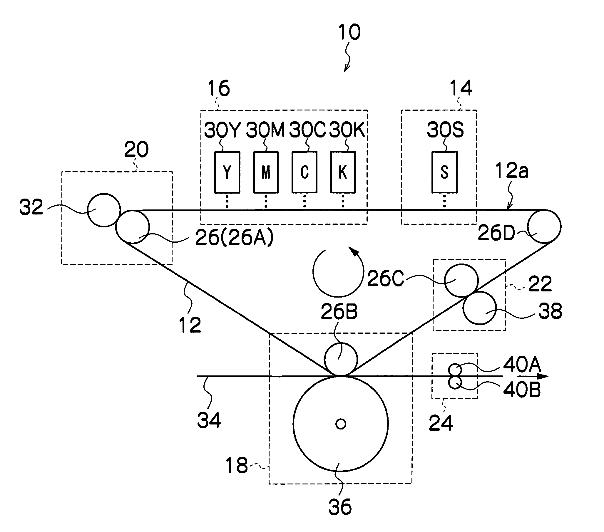
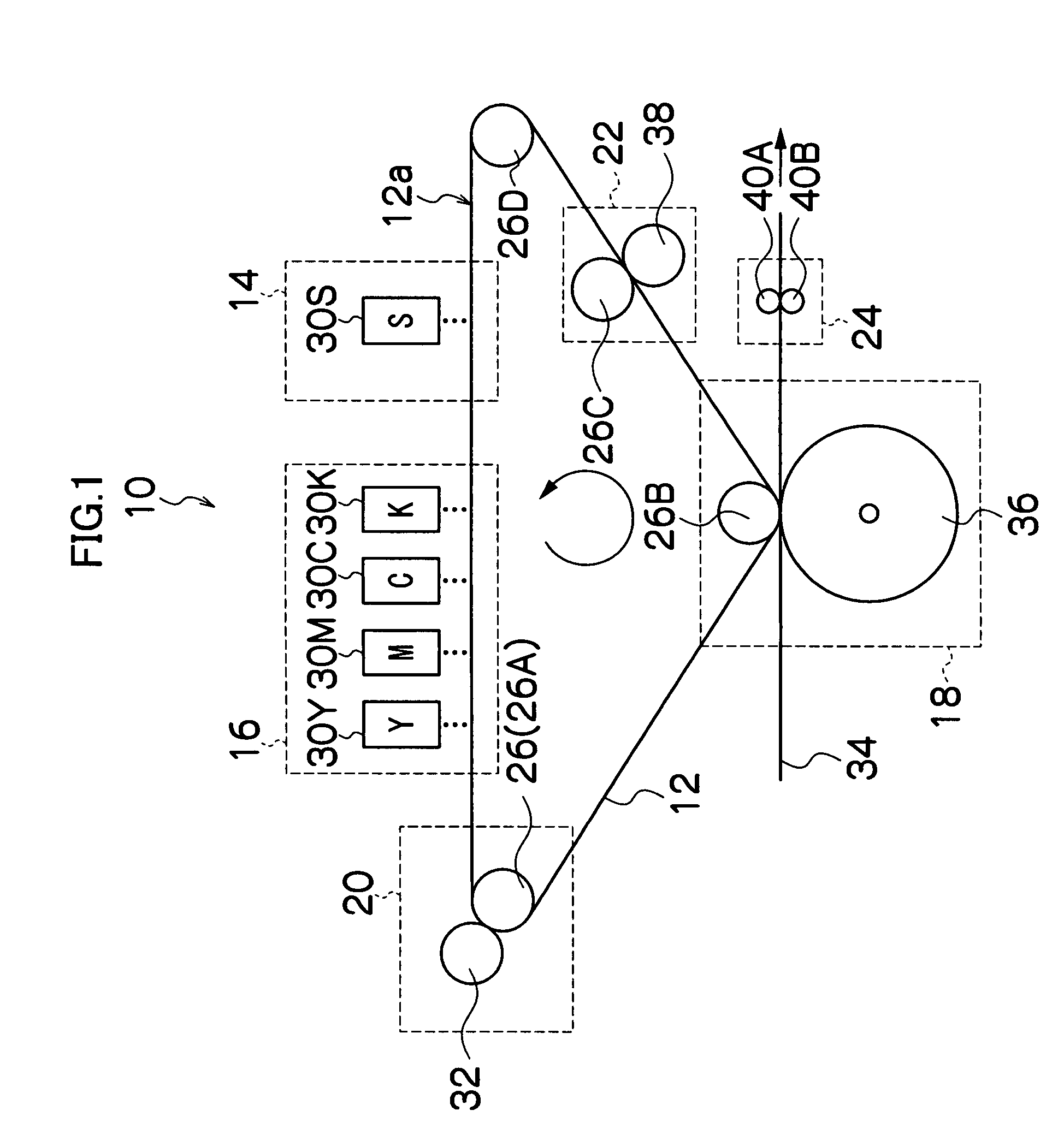
An image forming apparatus forms an image on a recording medium by transferring an image formed on an intermediate transfer body to the recording medium. The image forming apparatus includes: a first liquid deposition device which performs deposition of a first liquid onto the intermediate transfer body, the first liquid containing solvent-insoluble material; a second liquid deposition device which performs deposition of a second liquid onto the intermediate transfer body before the deposition of the first liquid, the second liquid having a function of causing the solvent-insoluble material to aggregate; and a deposition control device which controls the deposition in such a manner that a minimum thickness of a layer of the second liquid formed on the intermediate transfer body at the deposition of the first liquid is not smaller than 1 μm, and a volume of the deposition of the second liquid per unit surface area is not smaller than a volume of the deposition of the first liquid per unit surface area.

Description

BACKGROUND OF THE INVENTION[0001]1. Field of the Invention[0002]The present invention relates to an image forming apparatus and an image forming method, and more particularly to an intermediate transfer type image forming apparatus and method therefor, by which an image is formed on a recording medium by transferring an image formed on an intermediate transfer body to the recording medium.[0003]2. Description of the Related Art[0004]Inkjet recording apparatuses are known which use a so-called intermediate transfer system, in which an image is formed on an intermediate transfer body by a recording head (inkjet head), and the image formed on the intermediate transfer body is then transferred to a recording medium. In a recording apparatus in the related art, it is difficult to achieve high image quality as well as achieving good transfer characteristics on the intermediate transfer body. This is because intermediate transfer bodies that have good transfer and separation characteristic...

Claims


Application Information

Patent Timeline
Patent Type & Authority Patents(United States)
IPC IPC(8): B41J2/01
CPCB41J2/0057
Inventor YAHIRO, YASUKO
Owner FUJIFILM CORP
Why Eureka
Try Eureka