Refrigerator

a technology for refrigerators and freezers, applied in domestic cooling devices, lighting and heating devices, cabinets, etc., can solve the problem of user discomfort in using the freezing compartment mounted at the lower portion of the refrigerator, and achieve the effect of shortening the length of the conductor

Active Publication Date: 2010-08-31
LG ELECTRONICS INC
View PDF25 Cites 56 Cited by
  • Summary
  • Abstract
  • Description
  • Claims
  • Application Information

AI Technical Summary

Benefits of technology

[0009]An object of the present invention is to provide a refrigerator which can elevate a compartment provided at a lower portion of the refrigerator when the door is open for the user's convenience and a mechanism for electrically connecting a device for elevating the compartment with the body.
[0011]Another object of the present invention is to prevent a cable electrically connecting the electrical device with the body from being damaged by a movement of the door or other parts of the refrigerator.
[0015]In one embodiment, the conductor may include a first segment, and a second segment movable with respect to the first segment based upon the movement of the electrical device. The first and the second segments may be electrically connectable to or disconnectable from each other based upon the movement of the electrical device. The first and the second segments are overlappable with each other along a longitudinal direction of the conductor to shorten a length of the conductor. The first segment may be movable with respect to the second segment along a longitudinal direction of the conductor to lengthen or shorten a length of the conductor. The first segment may include a first terminal and the second segment may include a second terminal, wherein the first and the second terminals may be electrically connected when the door is open and may be electrically disconnected when the door is closed.
[0016]The refrigerator may further include a first rail and a second rail both for guiding a movement of the door. The conductor may include a first segment secured to the first rail, and a second segment secured to the second rail. The first and the second segments are electrically connectable to and disconnectable from each other based upon a movement of the door. The first segment may be arranged inside the first rail to be protected by the first rail and may have a first terminal exposed to an outside of the first rail to be contactable with the second segment. The second segment may be arranged on an outside surface of the second rail to prevent the second segment from being damaged by the first rail and may have a second terminal exposed to an inside of the second rail to be contactable with the first segment. The refrigerator may further include a protection cover secured to at least one of the rails to cover and protect a part of the conductor exposed to an outside of the rails.
[0019]Alternatively, the refrigerator may further include a foldable jointed cover, wherein the conductor may be arranged to pass through the foldable jointed cover. The foldable jointed cover may include a plurality of hollow segments coupled with each other by a pivot in series. A maximum angle, being able to be formed between two adjacent segments when the foldable jointed cover is fully unfolded, may be limited so as to prevent the foldable jointed cover from being slack.

Problems solved by technology

Meanwhile, it is very uncomfortable for the user to use the freezing compartment mounted at the lower portion of the refrigerator when the door is simply open by rotating about the hinge because the user has to kneel and bend his or her body and stretch his / her hands into an inside of the freezing compartment mounted at the lower portion of the refrigerator.

Method used


Image

  • Refrigerator
  • Refrigerator
  • Refrigerator

Examples


first embodiment

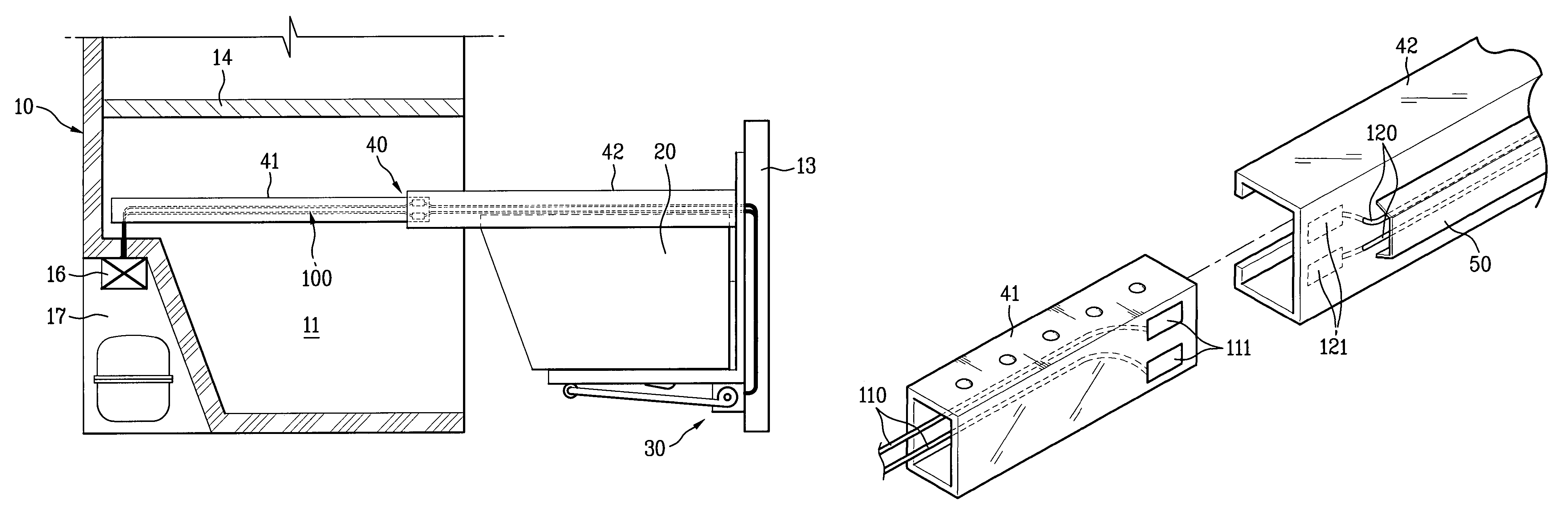
[0066]Therefore, in the first embodiment, the rails 41 and 42 work both as rails for guiding the container 20 and as conductor guides.

[0067]A variation of the refrigerator according to the first embodiment of the present invention is illustrated in FIG. 9. As shown in FIG. 9, a conductor guide 60, independent from the rails 41 and 42, is provided to the variation of the refrigerator according to the first embodiment. The conductor guide 60 is extendable and retractable along a longitudinal direction thereof based upon the movement of the electrical part, e.g., the elevating device 30, or the movement of the door 30.

[0068]The conductor guide 60 includes a first guide 61 secured to the body 10 of the refrigerator and a second guide 62 secured to the door 13 directly or a supporter firmly secured to the door 13. The first guide 61 is overlapped with the second guide 62 when the door 13 is closed by being inserted into the second guide 62 along a longitudinal direction of the second gui...

second embodiment

[0077]Alternatively, the conductor 100 having the coiled portion 130 may be arranged in or to pass through the conductor guide 60 independent from the rail 40 as shown in FIG. 10 as a variation of the In addition, the supplemental conductor guide 70 may be provided in the conductor guide 60 and the conductor 100 having the coiled portion 130 may be arranged in or to pass through the supplemental conductor guide 70. Alternatively, although not shown in the drawings, the conductor 100 having the coiled portion 130 may be directly arranged in or to pass through the rails 41 and 42 without the supplemental conductor guide 70 or the conductor guide 60. Further, it is possible that the conductor 100 having the coiled portion 130 may be arranged independently, not in any one of the rail 40, the conductor guide 60, or the supplemental conductor guide 70.

[0078]A third embodiment of the conductor 100 according to the present invention is shown in FIGS. 11 to 15B. Referring to the above drawi...


PUM


Abstract

A refrigerator includes a body; a compartment within the body; a container within the compartment, the container being moveable along a first direction; an electrical device, the electrical device moving along with the container in the first direction when the container moves along the first direction; and a conductor for providing an electrical signal to the electrical device, the conductor being extendable and retractable in the first direction when the electrical device moves along the first direction.

Description

[0001]This Nonprovisional application claims priority under 35 U.S.C. §119(a) on Patent Application No. 10-2004-0085688 filed in Korea on Oct. 26, 2004, Patent Application No. 10-2004-0091365 filed in Korea on Nov. 10, 2004, and Patent Application No. 10-2005-0049831 filed in Korea on Jun. 10, 2005, the entire contents of which are hereby incorporated by reference.BACKGROUND OF THE INVENTION[0002]1. Field of the Invention[0003]The present invention relates to a refrigerator, and more particularly, to a mechanism electrically connecting a body of the refrigerator with an electrical device which is mounted on a door or a part of the refrigerator movable with respect to the body of the refrigerator.[0004]2. Discussion of the Related Art[0005]Conventional refrigerators are usually classified into three types, i.e., a top mount freezer type, a side by side type, and a bottom mount freezer type. In the top mount freezer type refrigerator, a freezing compartment is provided at an upper por...

Claims


Application Information

Patent Timeline
Patent Type & Authority Patents(United States)
IPC IPC(8): A47B81/00A47B97/00
CPCA47B51/00F25D25/025F25D29/005F25D2400/40
Inventor OH, SEUNG HWANJEONG, KYUNG HANKIM, SANG OHLEE, MYUNG RYUL
Owner LG ELECTRONICS INC
Why Eureka
Try Eureka