
Ophthalmic solution dispensing device

a technology of ophthalmic solution and dispensing device, which is applied in the direction of spectacles/goggles, instruments, physical therapy, etc., can solve the problems of insufficient blinking, insufficient tear production of eyes, and insufficient tears

Inactive Publication Date: 2010-08-31
STINSON STEVE
View PDF15 Cites 10 Cited by
  • Summary
  • Abstract
  • Description
  • Claims
  • Application Information

AI Technical Summary

Benefits of technology

"The present invention provides a device for dispensing ophthalmic solutions to a user's eyes. The invention includes a clip on eye solution applicator that can be attached to eyeglasses. The clip has a container for holding the solution, transfer tubing for dispensing and applying the solution, and a clip for attaching the applicator to eyeglasses. The transfer tubing has one or two transfer holes, and the container and eyeglasses have corresponding transfer holes. The one-hole configuration makes it difficult to refill the clip on eye solution applicator, while the two-hole configuration aids in refilling. The invention provides a convenient and easy-to-use device for dispensing ophthalmic solutions."

Problems solved by technology

In dry eye syndrome, the eye doesn't produce enough tears, or the tears have a chemical composition that causes them to evaporate too quickly.
Another cause is insufficient blinking, such as when a person stares at a computer screen all day.
Long-term contact lens wear is another cause; in fact, dry eyes are the most common complaint among contact lens wearers.
Recent research indicates that contact lens wear and dry eyes can be a vicious cycle.
Dry eye syndrome makes contact lenses feel uncomfortable, and the rubbing of the lenses against the conjunctiva seems to be a cause of dry eyes.
Each layer is produced by a different part of the eye (the lacrimal gland produces the lacrimal layer, for example), so a problem with any of those sources can result in dry eyes.
Recent research suggests that smoking, too, can increase the risk of dry eye syndrome.
With increased popularity of eyelid surgery for improved appearance, dry eye complaints now occasionally are associated with incomplete closure of eyelids following a procedure.
This won't work unless the eye drops also contain artificial tears, and the original “get-the-red-out” formulation doesn't.
These drops can reduce or eliminate the redness temporarily, but they don't treat the cause of the redness, whether it's dryness, environmental irritation, or some other problem.

Method used


Image

  • Ophthalmic solution dispensing device
  • Ophthalmic solution dispensing device
  • Ophthalmic solution dispensing device

Examples


Embodiment Construction

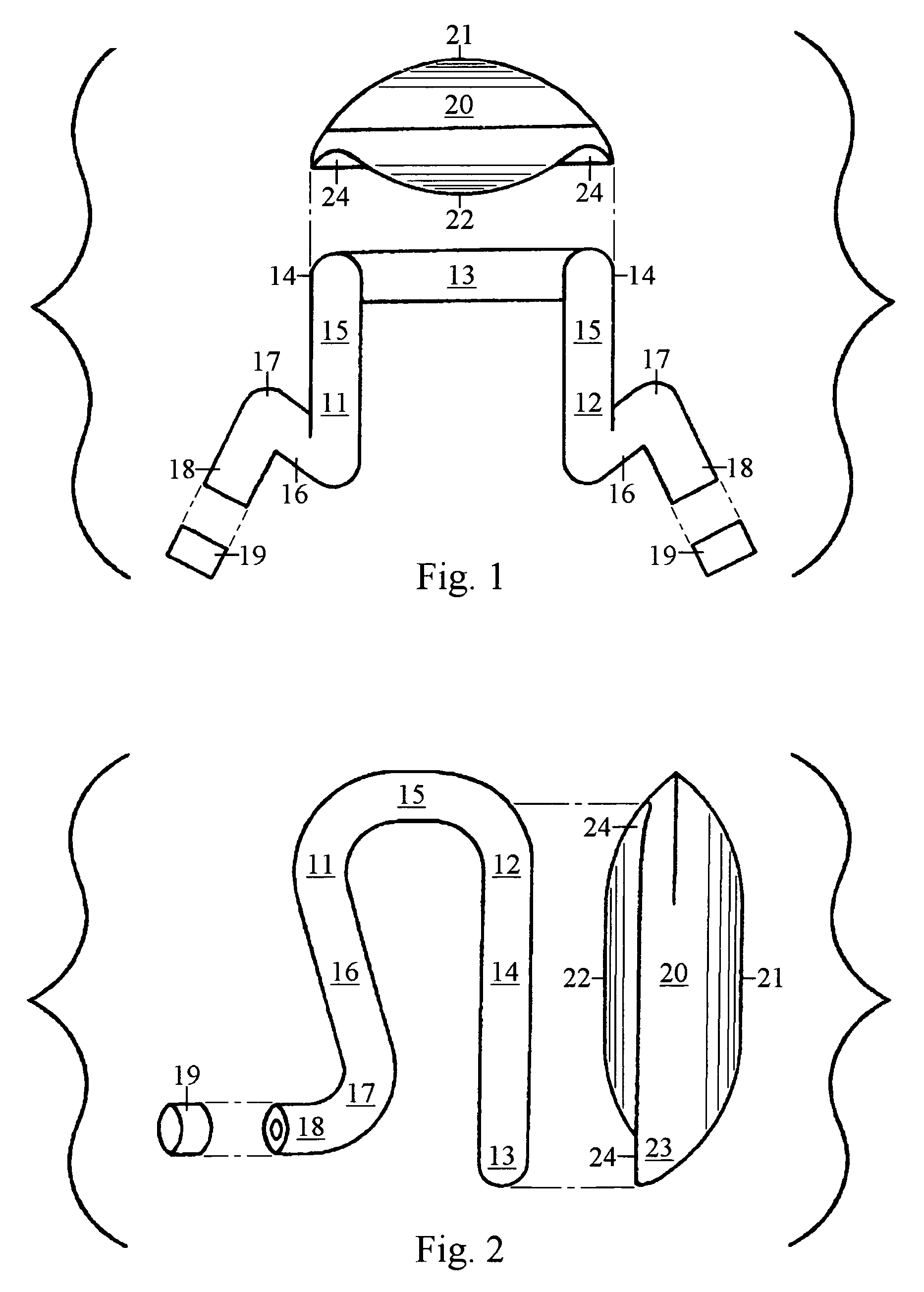
[0020]FIG. 1 is an exploded top view showing the transfer tubing, solution container and nozzle caps of the clip on eye solution applicator.

[0021]FIG. 2 is an exploded right side view showing the transfer tubing, solution container and nozzle caps of the clip on eye solution applicator.

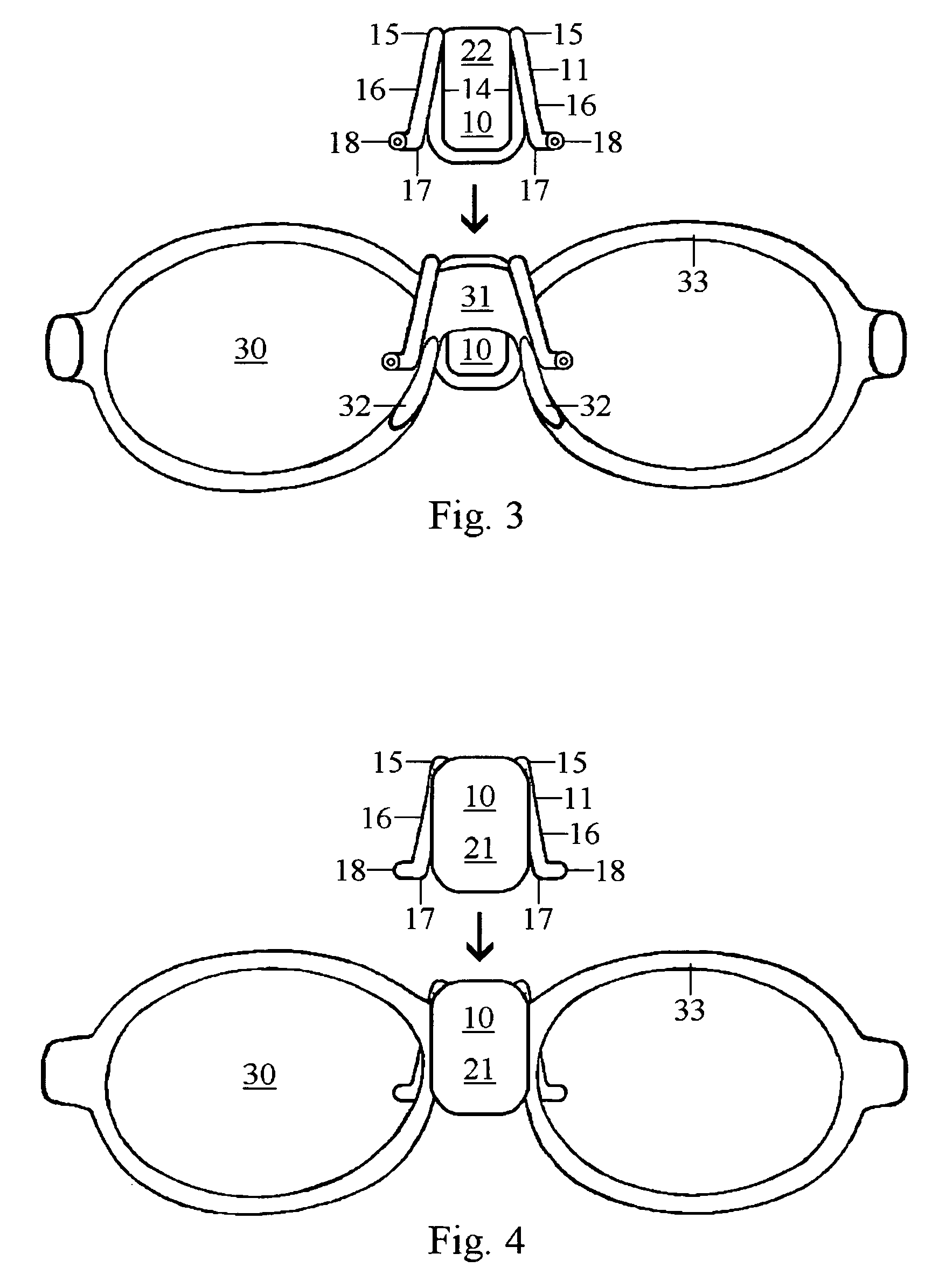
[0022]FIG. 3 is a view from behind a pair of common eyeglasses. This view shows the size perspective of the clip on eye solution applicator, how the applicator is clipped onto eyeglasses and how it would look from behind the eyeglasses.

[0023]FIG. 4 is a view from in front of a pair of common eyeglasses. This view shows the size perspective of the clip on eye solution applicator, how the applicator is clipped onto eyeglasses and how it would look from in front of the eyeglasses.

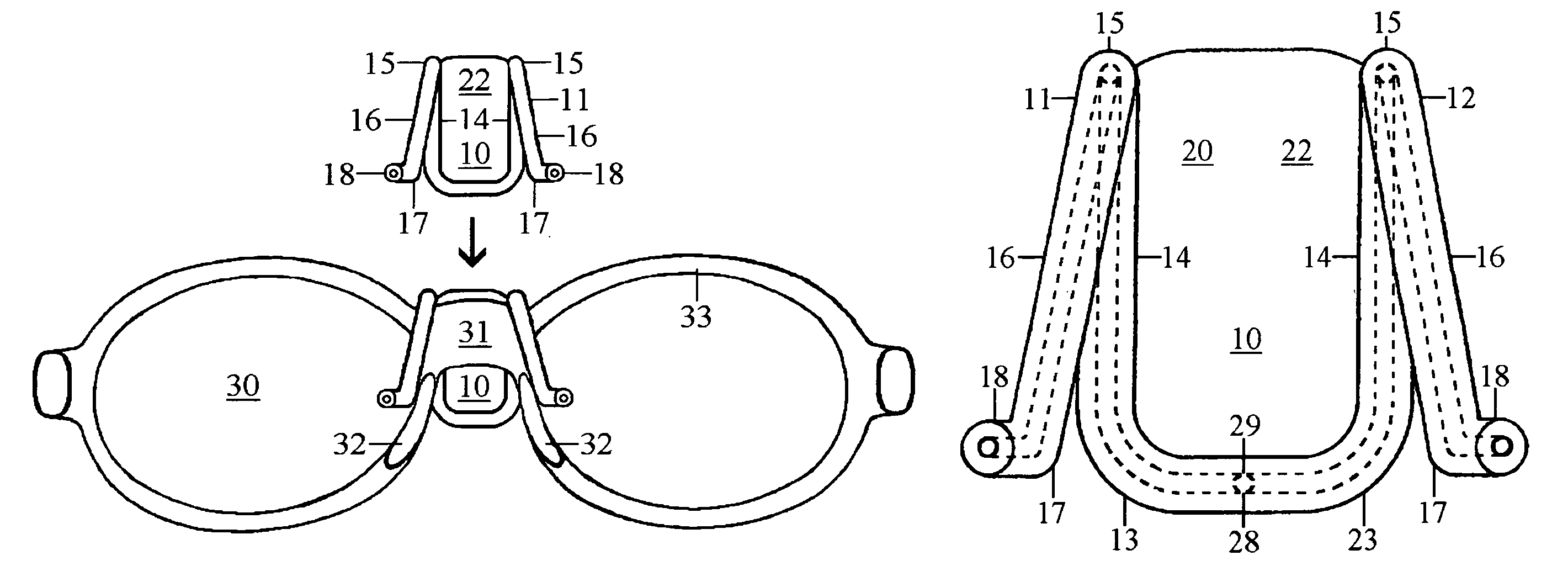
[0024]FIG. 5 is a back view showing the transfer tubing with the solution container behind it. This view shows the one hole configuration and fluid travel paths that make the clip on eye solution applicator difficult to refill.

[...


PUM


Abstract

A device for dispensing ophthalmic solutions to a user's eyes comprising a container for holding ophthalmic solutions, transfer tubing attached to the container for dispensing and applying said solution and a clip attached to the container for attaching said applicator to eyeglasses. The transfer tubing is the clip by being formed into the shape of a clip for attaching said eye solution applicator to eyeglasses.

Description

FIELD OF THE INVENTION[0001]The present invention relates to the field of ophthalmic solution dispensing devices. More specifically, the present invention relates to ophthalmic solution dispensing devices that are mountable onto glasses for easy solution dispensing.BACKGROUND[0002]Tears bathe the eye, washing out dust and debris and keeping the eye moist. They also contain enzymes that neutralize the microorganisms that colonize the eye. Tears are essential for good eye health.[0003]In dry eye syndrome, the eye doesn't produce enough tears, or the tears have a chemical composition that causes them to evaporate too quickly.[0004]Dry eye syndrome has several causes. It occurs as a part of the natural aging process, especially during menopause, as a side effect of many medications, such as antihistamines, antidepressants, certain blood pressure medicines, Parkinson's medications, and birth control pills; or dry, dusty or windy climates. Home or office air conditioning or a dry heating ...

Claims


Application Information

Patent Timeline
Patent Type & Authority Patents(United States)
IPC IPC(8): G02C1/00A61M35/00
CPCA61F9/0026G02C9/04G02C11/00
Inventor STINSON, STEVE
Owner STINSON STEVE
Learn More