Radar system for motor vehicles

a technology for motor vehicles and radars, applied in vehicle components, instruments, measurement devices, etc., can solve the problems of inability to track the data on other objects, inability to accurately measure the relative velocity of objects, and inability to accurately measure the relative velocity, etc., to achieve a substantially simplified evaluation procedure, improve the accuracy of velocity measurement, and improve the effect of temporal resolution

Inactive Publication Date: 2010-08-31
ROBERT BOSCH GMBH
View PDF8 Cites 12 Cited by
  • Summary
  • Abstract
  • Description
  • Claims
  • Application Information

AI Technical Summary

Benefits of technology

[0009]The exemplary embodiment and / or the exemplary method of the present invention having the features described herein advantageously enables a more precise determination of the impact velocity to be made, making it possible for the function of the precrash system to be optimized particularly with regard to the impact velocity.
[0012]Therefore, in the case of an imminent collision, the exemplary embodiment and / or the exemplary method of the present invention provides for the switch to be made to a different measurement mode that is specifically configured for a more precise measurement of the relative velocity. In this context, it is possible to limit the evaluation to the collision object and to dispense with collecting distance data, so that the evaluation procedure may be substantially simplified and, accordingly, the cycle time shortened, thereby achieving a higher temporal resolution in the velocity measurement. In this manner, it is possible to measure the relative velocity of the collision object more precisely and to track the same virtually up to the time of collision, so that the estimated value for the impact velocity obtained during the regular measurement mode of the radar sensor may be corrected and defined more precisely.
[0013]In the velocity measurement mode, the need for modulating the frequency of the transmitted radar signal is eliminated, and a pure Doppler measurement of the relative velocity of the collision object is taken. This substantially simplifies the evaluation and considerably reduces the cycle time, while a high level of precision is maintained for the relative velocity measurement.
[0014]By integrating the relative velocity data recorded in the velocity measurement mode, the temporal change in the distance may also continue to be tracked, making it possible to further improve the estimated value for the time of collision.

Problems solved by technology

On the one hand, in such a situation, it is already only the location-detection data on the collision object that are relevant, so that it is inexpedient to track the data on the other objects.
For that reason, as the collision object get progressively closer, the distance data become increasingly unreliable and ultimately useless.
Therefore, the assumption that the relative velocity of the object remains the same during two consecutive frequency ramps no longer holds unconditionally, so that even the accuracy of the velocity measurement is degraded.

Method used


Image

  • Radar system for motor vehicles
  • Radar system for motor vehicles
  • Radar system for motor vehicles

Examples


Embodiment Construction

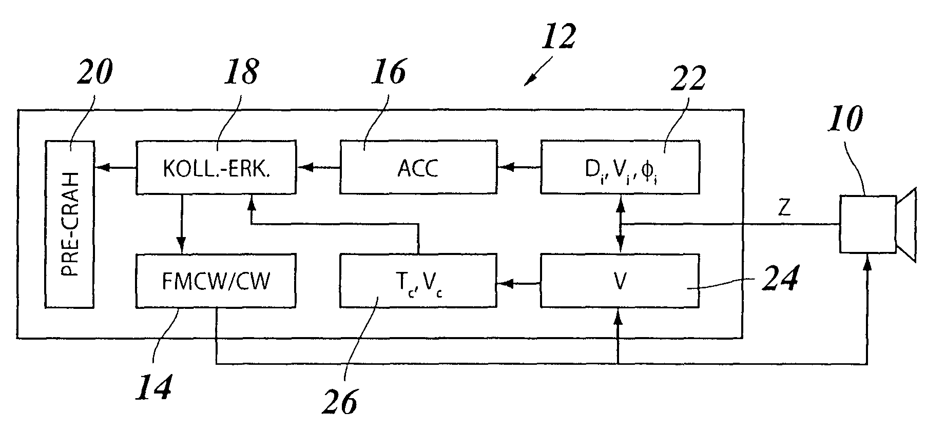
[0019]The radar system shown in FIG. 1 includes a radar sensor 10, for example a 77 GHz long-range radar, that is installed in the front part of the motor vehicle, and a corresponding electronic evaluation device 12, made up, for example, of one or more microprocessors, corresponding program memories and data memories, and the like. Evaluation device 12 also includes a driver 14 for controlling radar sensor 10. This driver is switchable between two operating modes FMCW und CW, as will be clarified later in greater detail. In the illustrated example, other components of evaluation device 12 include an ACC module 16, a collision detection device 18, and a precrash system 20.

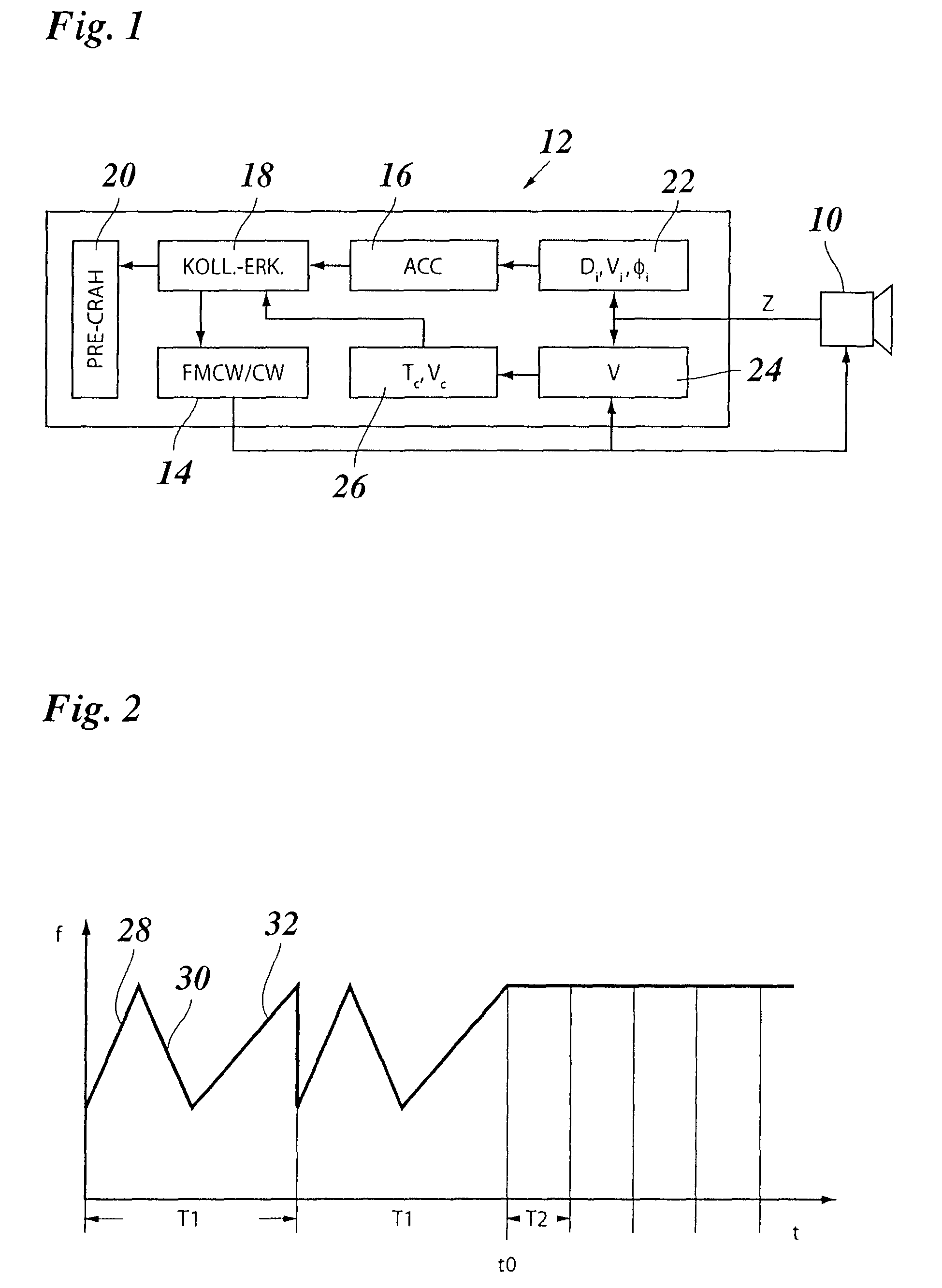
[0020]In normal operation, the ACC module is active, and radar sensor 10 is operated in the FMCW mode. In a manner known per se, in radar sensor 10, the transmitted radar signal is mixed with the radar signal that is reflected off of various objects, for example off of preceding vehicles, and received by the radar ...


PUM


Abstract

A radar system for motor vehicles, having a radar sensor and an evaluation device for measuring distances and relative velocities of objects in the surrounding field of the vehicle, and a collision detection device, which, on the basis of the measured distances and relative velocities, recognizes an imminent collision and delivers data on the expected time of collision and the impact velocity to a precrash system. The radar sensor is switchable by the collision detection device to a velocity measurement mode in which a more precise measurement of the relative velocity is made.

Description

FIELD OF THE INVENTION[0001]The present invention relates to a radar system for motor vehicles, having a radar sensor and an evaluation device for measuring distances and relative velocities of objects in the surrounding field of the vehicle, and a collision detection device, which, on the basis of the measured distances and relative velocities, recognizes an imminent collision and delivers data on the expected time of collision and the impact velocity to a precrash system.BACKGROUND INFORMATION[0002]A radar system of this kind is typically used in connection with an adaptive cruise control (ACC), which automatically adjusts the velocity of the host vehicle to the velocity of a preceding vehicle, to ensure that this preceding vehicle is followed at an appropriate collision-avoidance distance.[0003]In an FMCW (frequency modulated continuous wave) radar commonly used for these purposes, the frequency of the transmitted radar signal is periodically modulated using different ramp slopes...

Claims


Application Information

Patent Timeline
Patent Type & Authority Patents(United States)
IPC IPC(8): G01S13/00G01S13/931
CPCB60R21/0134G01S13/343G01S13/345G01S13/536G01S13/931G01S13/584G01S2013/9375G01S2013/9321G01S2013/9325G01S2013/9346G01S2013/93185G01S2013/93271
Inventor HILSEBECHER, JOERGOLBRICH, HERBERTSOHNKE, THORSTENKUTTENBERGER, ALFREDTHEISEN, MARCRANDLER, MARTINBUNSE, MICHAEL
Owner ROBERT BOSCH GMBH
Why Eureka
Try Eureka