Method for forming a stator core

a stator core and core technology, applied in the field of core slot insulators, can solve the problems of compromising the integrity of the required electrical isolation, defective stator assemblies, and increased so as to reduce the inherent spring force, less secure, and the effect of increasing the potential for this defect to occur

Active Publication Date: 2010-09-07
BORGWARNER INC
View PDF10 Cites 24 Cited by
  • Summary
  • Abstract
  • Description
  • Claims
  • Application Information

AI Technical Summary

Benefits of technology

[0005]The slot liner insulation must protect the slot segments from the sides of the slot as well as the back of the slot. The slot liner is placed between the walls of the core slot and the slot segments of the windings. It protects the wire from electrically grounding to the core during the process of making the stator as well as for the life of the stator in operation.
[0006]The typical process is to insert the slot liner material into the core slots and then radial insert the winding into the insulated core slots. For the continuous winding, cascaded or interlaced, the slot segments of the winding are desired to be substantially radially inserted from the inner diameter of the stator core through the slot opening to a final position of being housed into the insulated slots. During the insertion process, the slot segments must pass by the inner edge of the slot liner. If the slot liner is not properly secured to the sides of the slots, the edge of the slot liner may be caught by the slot segments and thereby compromising the integrity of the required electrical isolation between the slot segments and the core slot. If this were to happen, the slot segment becomes exposed to the steel of the core slot leading to a winding with an electrical ground and thereby resulting is a defective stator assembly. The potential for this defect to occur is increased for a high slot fill stator assembly because a high slot fill stator requires a thin slot liner and a thin slot liner has less inherent spring force and therefore is less secured to the edges of the core slot. A high slot fill stator assembly requires an insulator thickness that is less than 0.2 millimeter thick. The insulator thickness is defined as to not include any thickness inherent to an adhesive that may be applied to the insulator or in between the insulator and the sides of the core slots. The potential for this defect to occur is also increased when rectangular shaped slot segments are inserted the core slots because the corner of the slot segments can easily catch the edge of the slot liner. For this reason, the rectangular shaped slot segments may often have a radius between two adjacent edges to eliminate the corner. The potential for this defect to occur is also increased when the flexibility of the slot segment is large enough such that during the insertion process, the slot segment flexes in the circumferential direction and thereby interfering with and catching the slot liner edge. The flexibility becomes an issue when the circumferential width of the slot segments is less than two millimeter. The potential for this defect to occur is also increased for the cascaded winding compared to the interlaced winding because the interlaced winding is comprised of a majority of end loop segments which each connect a slot segment housed in a forward radial position with a slot segment housed in a rearward radial position which results in a “locking” effect of all of the end loop segments and slot segments, which creates a very rigid winding wherein the flexibility of the slot segments is reduced.
[0008]The design of the stator assembly along with the process of radial insertion of the windings in accordance with the present invention advantageously eliminates the potential of catching the edge of the slot liner, thereby damaging the integrity of the insulation and thereby leading to an electrical ground between the windings and the core. The slot liner is not potentially damaged because it is placed securely against the sides of the slot during the insertion process. In a first embodiment of the present invention, the slot liner is adhered to the sides of the slots. In a second embodiment of the present invention, tooling is inserted into the insulated slots prior to inserting any slot segments. In a third embodiment of the present invention, the slot liner insulation material is adhered to a thin sheet of a spring material, for example steel. In the fourth embodiment of the present invention, the slot liner material is replaced by a very thin coating.

Problems solved by technology

If the slot liner is not properly secured to the sides of the slots, the edge of the slot liner may be caught by the slot segments and thereby compromising the integrity of the required electrical isolation between the slot segments and the core slot.
If this were to happen, the slot segment becomes exposed to the steel of the core slot leading to a winding with an electrical ground and thereby resulting is a defective stator assembly.
The potential for this defect to occur is increased for a high slot fill stator assembly because a high slot fill stator requires a thin slot liner and a thin slot liner has less inherent spring force and therefore is less secured to the edges of the core slot.
The potential for this defect to occur is also increased when rectangular shaped slot segments are inserted the core slots because the corner of the slot segments can easily catch the edge of the slot liner.
The potential for this defect to occur is also increased when the flexibility of the slot segment is large enough such that during the insertion process, the slot segment flexes in the circumferential direction and thereby interfering with and catching the slot liner edge.
The flexibility becomes an issue when the circumferential width of the slot segments is less than two millimeter.

Method used


Image

  • Method for forming a stator core
  • Method for forming a stator core
  • Method for forming a stator core

Examples


second embodiment

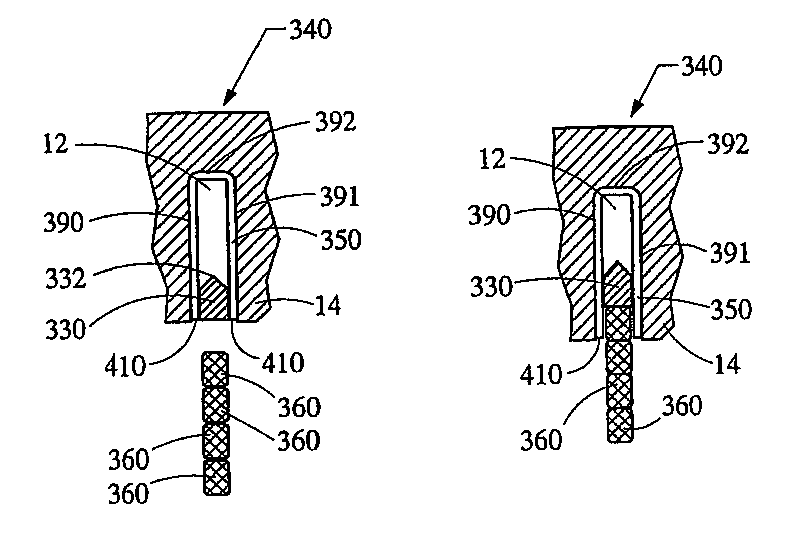
[0032]Now referring to FIG. 5, the present invention is shown as an insulated core slot 340 having tooling, indicated generally at 330, inserted into the insulated slots 340 prior to inserting the slot segments 360. The circumferential width of the tooling 330 preferably fits closely to the width of the insulated slot 340. To prevent the tooling 330 from catching the edges 310 of the insulator 350, similarly to the slot segments 360 catching the edges 310, the tooling 330 includes a point, indicated generally at 332, and is inserted in the radial direction 24 into the core slots 12.

[0033]Alternatively, the tooling 330 could include a point (not shown) on the axial end of the tooling 330, wherein the tooling 330 is inserted in the axial direction 16 into the core slots 12. In either case, radial point 332 or axial point (not shown), the point enters the core slots 12 prior to the rest of the tooling 330 which ensures that the edges 290 and 291 of the insulator 350 are not caught by t...

third embodiment

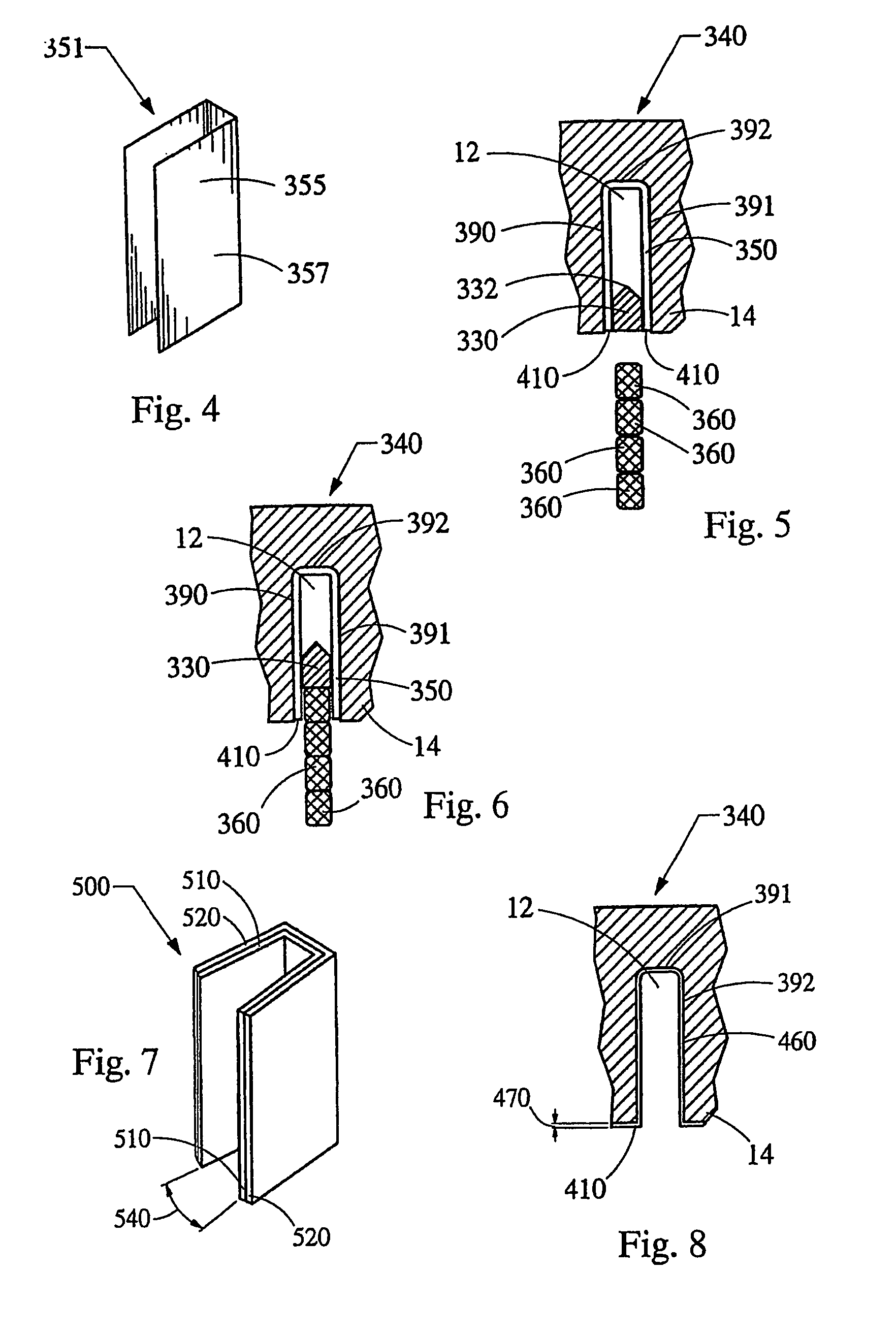
[0036]Referring now to FIG. 7, a laminate, indicated generally at 500, of the present invention is shown. The laminate 500 is composed of at least two members, an insulator member, indicated generally at 510 and a spring member, indicated generally at 520 which are laminated or adhered together, typically by an adhesive applied in between the members 510 and 520. After assembly into a core slot 12, the insulator member 510 provides the necessary electrical isolation between the slot segments 360 and the core slots 12 and the spring member 520 provides a spring force, which secures the laminate 500 to the sides 390 and 391 of the core slots 12. The memory properties inherent to the properties of the spring member 520 cause the laminate 500, prior to insertion into a core slot 12, to have an angle, indicated generally at 540, between opposing sides of the laminate 500 to be greater than zero.

[0037]When the laminate 500 is inserted into a core slot 12, the sides 390 and 391 of the core...

fourth embodiment

[0039]Referring now to FIG. 8, a fourth embodiment to the present invention is shown as an insulated core slot 340 wherein the insulation is composed of a coating, indicated generally at 460 having a very thin thickness, generally indicated at 470. The coating must be thin to allow for a high slot fill winding having minimum insulation in the core slots 12 and to prevent the buildup on the inner surface 14 of the core 10 which could potentially interfere with the spinning rotor which is located radially inward of the inner surface 14. The high slot fill stator assembly, by definition, has very thin insulation and therefore to be considered a high slot fill stator, the thickness 470 of the coating 460 must be less then 0.2 millimeter.

[0040]The cascaded winding for the stator is shown in FIGS. 9 through 9c. Each of the continuous conductors have a plurality of slot segments disposed in the core slots 12. The term continuous, utilized herein, refers to a conductor including end loops s...


PUM

PropertyMeasurementUnit
circumferential widthaaaaaaaaaa
thicknessaaaaaaaaaa
circumferential widthaaaaaaaaaa

Abstract

A stator of a rotary electric machine having secured core slot insulators includes a multi-phase stator winding, having a plurality of slot segments that are adapted to be radially inserted into a plurality of circumferentially spaced axially-extending core slots in a surface of a cylindrically-shaped stator core. The stator winding includes the plurality of slot segments alternately connected at the first and second ends of the stator core by a plurality of end loop segments to form the winding. The plurality of core slots house an insulator to electrically isolate the slot segments from the core slots. The insulator is secured to the sides of the core slot prior to the process of radial inserting the plurality of slot segments into the plurality of core slots of the cylindrically-shaped stator core.

Description

BACKGROUND OF THE INVENTION[0001]The present invention relates generally to electric machines and, in particular, to a core slot insulator for an electric machine having a core and a winding. Electric machines, such as alternating current electric generators, or alternators are well known. Prior art alternators typically include a stator assembly and a rotor assembly disposed in a alternator housing. The stator assembly is mounted to the housing and includes a generally cylindrically-shaped stator core having a plurality of slots formed therein. The rotor assembly includes a motor rotor attached to a generally cylindrical shaft that is rotatably mounted in the housing and is coaxial with the stator assembly. The stator assembly includes a plurality of wires wound thereon, forming windings. The stator windings are formed of slot segments that are located in the core slots and end loop segments that connect two adjacent slot segments of each phase and are formed in a predetermined mul...

Claims


Application Information

Patent Timeline
Patent Type & Authority Patents(United States)
IPC IPC(8): H02K15/00
CPCH02K3/345H02K15/10H02K1/16H02K3/12H02K3/28Y10T29/49012Y10T29/53143Y10T29/49011Y10T29/49009
Inventor NEET, KIRK E.
Owner BORGWARNER INC
Why Eureka
Try Eureka