Brake Force Generating Device for a Hydraulic Vehicle Brake System, Vehicle Brake System and Method for Operating a Brake Force Generating Device

Inactive Publication Date: 2009-12-17
SCHLUTER PETER +4
View PDF12 Cites 0 Cited by
  • Summary
  • Abstract
  • Description
  • Claims
  • Application Information

AI Technical Summary

Benefits of technology

[0006]It is a feature of the present invention to provide a brake force generating device of the initially described kind, which enables reliable mechanical uncoupling of the brake force generation from the mechanically actuated brake pedal, but which allows adequate brake force generation in an emergency operating situation by immediate employment of the actuating force generated on the brake pedal.

Problems solved by technology

Furthermore, displacements of the force input member arising from a brake pedal actuation do not lead immediately and necessarily to corresponding brake force generation.

Method used


Image

  • Brake Force Generating Device for a Hydraulic Vehicle Brake System, Vehicle Brake System and Method for Operating a Brake Force Generating Device
  • Brake Force Generating Device for a Hydraulic Vehicle Brake System, Vehicle Brake System and Method for Operating a Brake Force Generating Device

Examples


Embodiment Construction

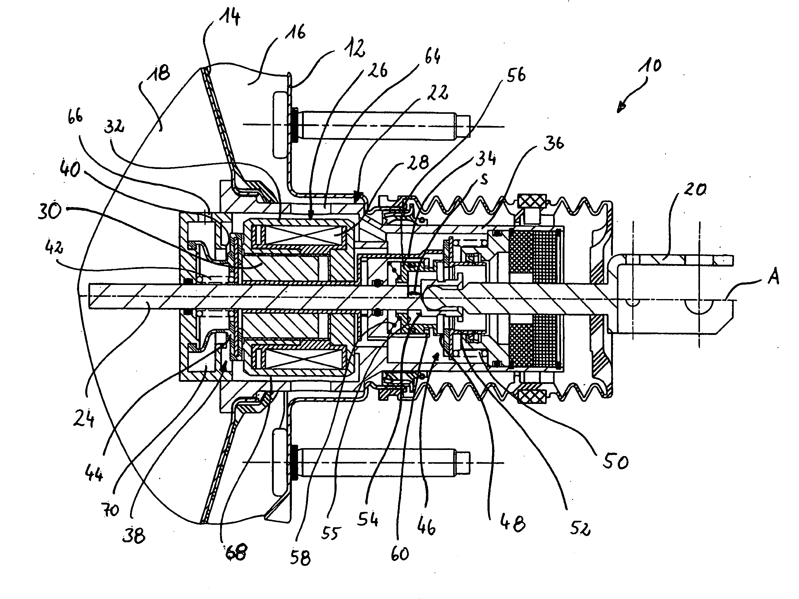
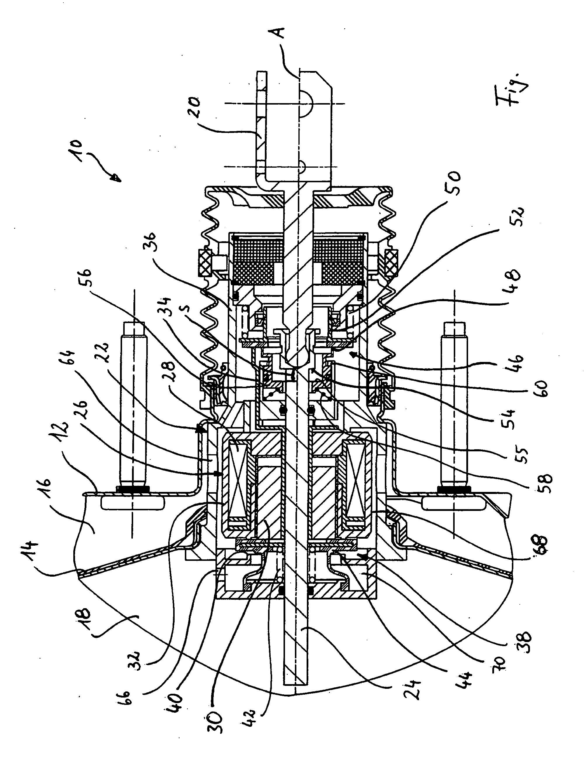
[0027]In the figure a brake force generating device 10 with a brake force generating device housing 12 is illustrated, which is divided into a working chamber 16 and a vacuum chamber 18 by a movable wall 14. The vacuum chamber 18 is connected to a vacuum source, not shown. The working chamber 16 and the vacuum chamber 18 can be triggered via a control valve device 22, as will be explained in detail below.

[0028]The brake force generating device 10 further has a force input member 20, displaceable along a longitudinal axis A and coupled to a brake pedal, not shown. The force input member 20 is further connected to a transmission piston 24. The brake force generating device 10 is further connected to a master cylinder to transmit force, which is not shown in the figure.

[0029]The brake force generating device 10 has an electromagnetic actuating arrangement 26, comprising a magnetic coil 28 and a magnetic armature 30. The magnetic coil 28 is coupled to a magnetic coil housing 32. The mag...


PUM


Abstract

The invention relates to a brake force generating device for a hydraulic vehicle brake system with a force input member, which can be or is coupled to a brake pedal, a master cylinder arrangement for generating a hydraulic brake pressure, a chamber arrangement, in which a working chamber is separated from a vacuum chamber via a movable wall, a control valve device with a control valve housing for optional connection of the vacuum chamber to the working chamber or of the working chamber to the atmosphere and an electrically triggerable actuating device for actuating the control valve device, which is positioned as floating in the control valve housing. According to the invention it is provided that the control valve device has a first seal seat and a second seal seat, the seal seats being arranged on opposite sides of the actuating device in respect of the longitudinal axis. The invention provides that in a normal operating situation the force input member is mechanically uncoupled from the control valve device actuated by the actuating device. In an emergency operating situation, however, the force input member can according to the invention be coupled mechanically to the control valve device and can actuate the control valve device as a result of its displacement in the direction of the longitudinal axis.

Description

CROSS-REFERENCE TO RELATED APPLICATIONS[0001]This application is the National Stage of International Application No. PCT / EP2006 / 011844 filed Dec. 8, 2006, the disclosures of which are incorporated herein by reference in their entirety, and which claimed priority to German Patent Application No. 10 2005 061 598.8 filed Dec. 22, 2005, the disclosures of which are incorporated herein by reference in their entirety.BACKGROUND OF THE INVENTION[0002]The present invention relates to a brake force generating device for a hydraulic vehicle brake system with a force input member, which is displaceable along a longitudinal axis and is or can be coupled to a brake pedal, a chamber arrangement, in which a working chamber is separated from a vacuum chamber via a movable wall, a control valve device with a control valve housing, the control valve device having a first seal seat for optional connection of the vacuum chamber to the working chamber and a second seal seat for optional connection of th...

Claims


Application Information

Patent Timeline
Patent Type & Authority Applications(United States)
IPC IPC(8): B60T8/32B60T13/72
CPCB60T8/4077Y10T477/80B60T13/72B60T13/57
Inventor SCHLUTER, PETERSCHLUTER, FRANKSCHLUTER, ALEXANDERSCHLUTER, STEFANGERDT, IRINA
Owner SCHLUTER PETER
Why Eureka
Try Eureka