Pneumatically controllable weft thread clamp for a weaving machine

a weft thread clamp and pneumatic control technology, which is applied in weaving, textiles and papermaking, looms, etc., can solve the problems of unnecessary additional adjustments per weft thread clamp, the weft thread clamp has a longer lifespan, etc., and achieves less spring force and reduces the weight of the weft thread clamp

Inactive Publication Date: 2007-05-22
N V MICHEL VAN DE WIELE
View PDF18 Cites 0 Cited by
  • Summary
  • Abstract
  • Description
  • Claims
  • Application Information

AI Technical Summary

Benefits of technology

[0012]With such an embodiment, it is primarily the mass of the moveable jaw that determines the reaction speed of the weft thread clamp. If the jaw is manufactured as a light component, by keeping the size small or by using light materials, for example plastics, or a combination of both, the low inertia of this component allows it to be moved very easily and very quickly via fluid. In this way, a weft thread clamp with an exceptionally high reaction speed can be obtained that is capable of working reliably on a weaving machine with a very high weaving speed. Moreover, positive control of the closing movement is used, and the weft thread clamp can be produced very simply.
[0031]If the weft thread clamp is installed in such a way that the moveable jaw is located under the fixed jaw, gravity contributes to the spring force in moving the moveable jaw to the opened position. This allows the use of a spring element with less spring force. This can make possible a further reduction in weight for the weft thread clamp.

Problems solved by technology

The absence of the membranes, which are sensitive to wear, means that this weft thread clamp also has a longer lifespan than the existing weft thread clamps.
This makes additional adjustments per weft thread clamp unnecessary.

Method used


Image

  • Pneumatically controllable weft thread clamp for a weaving machine
  • Pneumatically controllable weft thread clamp for a weaving machine

Examples


Embodiment Construction

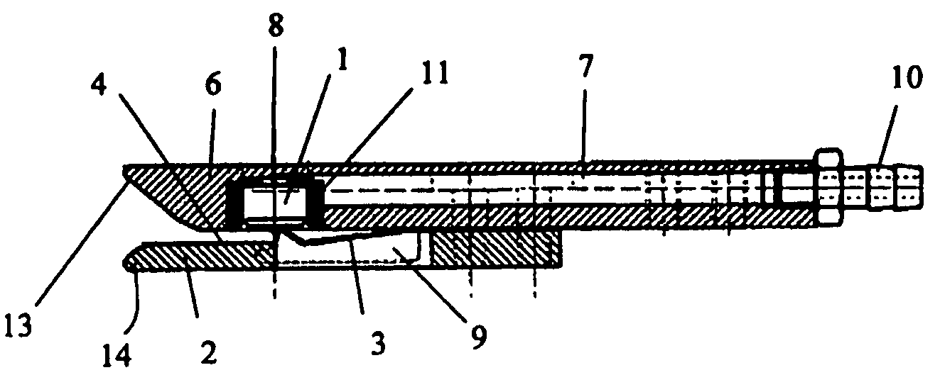
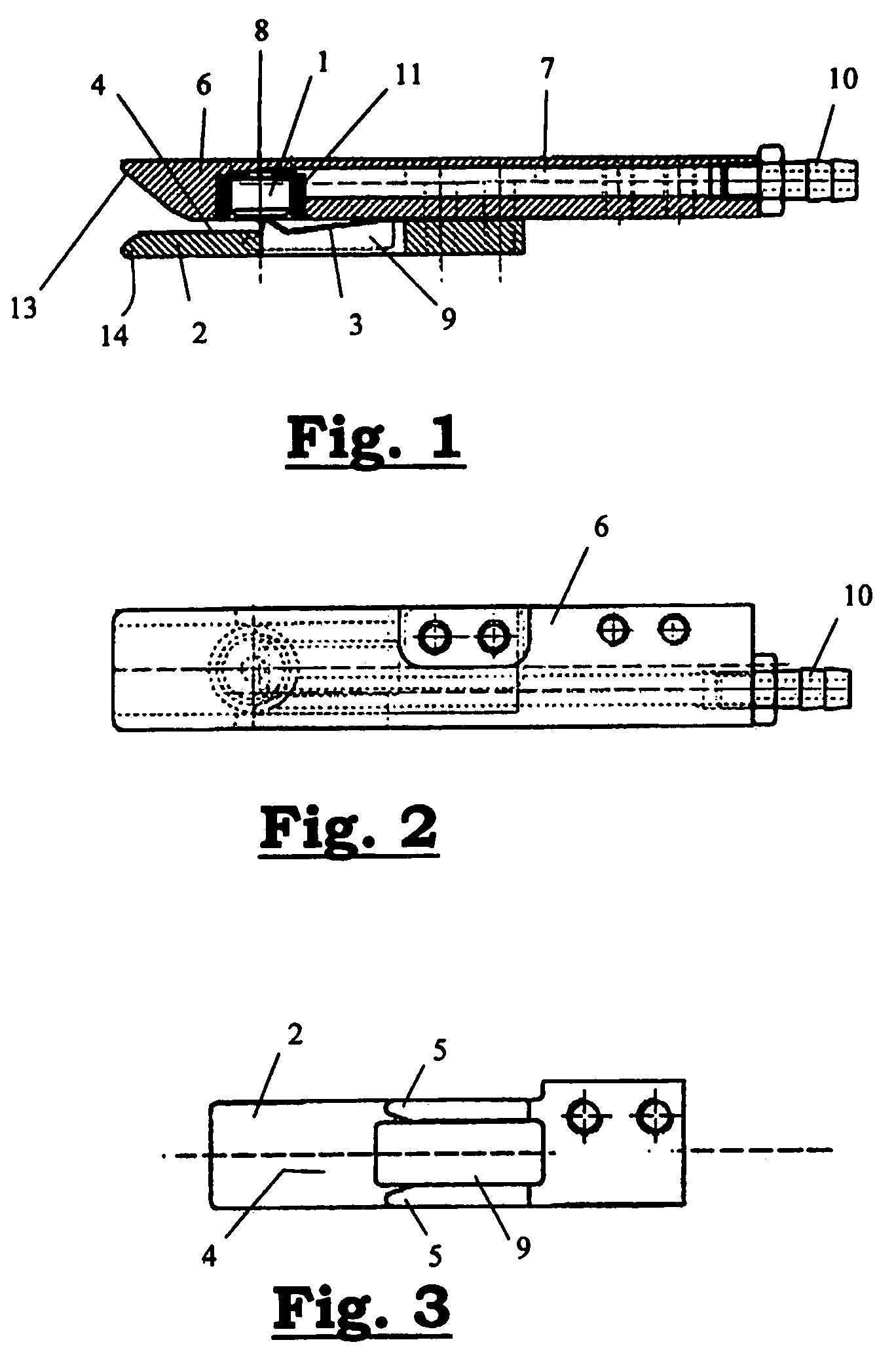
[0037]The weft thread clamp represented in the figures consists of an upper body (6) in which a compressed air channel (7) is provided that can be connected on one end via a connection piece (10) to a supply line that is not depicted in the figures. Close to the other end there is a cylindrical sleeve (11) in the body (6) contained in a notch provided for it. The sleeve (11) borders a cylindrical chamber that is open along the underside and that is connected to the compressed air channel (7) along the top. A suitable cylindrical pin (1) is provided in the cylindrical chamber that borders this sleeve (11). This pin, under the influence of the compressed air pressure, can be moved vertically in this chamber and functions as moveable jaw. Possible means of sealing can be provided (not on the figures shown) to prevent compressed air leaks.

[0038]On the upper face of the pin (1) there is also a cylindrical protuberance (8) that is designed to maintain a distance between the face and the u...


PUM


Abstract

This invention concerns a weft thread clamp with two jaws (1), (2) that can be moved to an opened and closed position, with at least one jaw (1) being directly moveable to the closed position via fluid pressure. The moveable jaw is preferably (1) a moveable unit, preferably made of a light material or in a compact form, which is moveable as a complete unit under the influence of the fluid pressure. Such a weft thread clamp is more reliable and simpler, and has a quicker reaction speed than the known pneumatically controllable weft thread clamps. This invention also concerns a system for the presentation of weft threads to a weaving machine equipped with one or more such weft thread clamps, as well as a weaving machine equipped with such a presentation system.

Description

[0001]This application claims the benefit of Belgian Application No. 2004 / 0251 filed May 19, 2004, which is hereby incorporated by reference in its entirety.BACKGROUND OF THE INVENTION [0002]This invention concerns a weft thread clamp for a weaving machine containing two jaws that can be put in an open and closed position, with at least one jaw being directly moveable by fluid pressure to the closed position.[0003]This invention also concerns a weaving machine equipped with one or more such weft thread clamps.[0004]EP 1,266,986 describes a weft thread clamp with a pneumatically controlled jaw that contains an air bellows in which atmospheric pressure is built up to increase the volume of the air bellows in order to move a leaf spring to a clamping position. Thus, here this leaf spring functions as a means of clamping. Only the closing movement is controlled positively by this clamp. The movement to the opened position occurs by allowing the atmospheric pressure to decrease such that...

Claims


Application Information

Patent Timeline
Patent Type & Authority Patents(United States)
IPC IPC(8): D03D47/34D03D47/27D03D47/38
CPCD03D47/125D03D47/34D03D47/38
Inventor MAES, DOMINIQUEDEJAEGERE, FERDI
Owner N V MICHEL VAN DE WIELE
Why Eureka
Try Eureka