Stator of a rotary electric machine having secured core slot insulators
- Summary
- Abstract
- Description
- Claims
- Application Information
AI Technical Summary
Benefits of technology
Problems solved by technology
Method used
Image
Examples
second embodiment
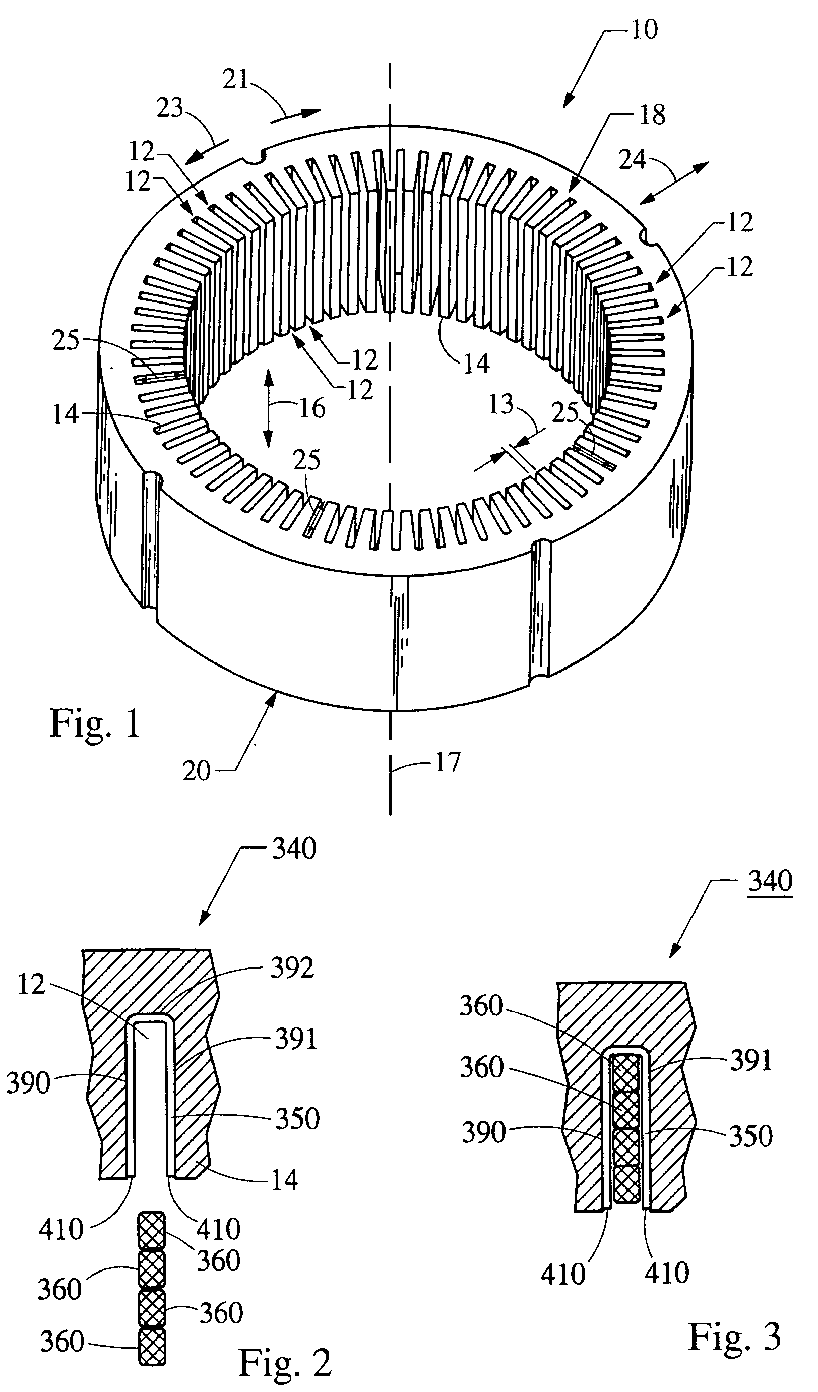
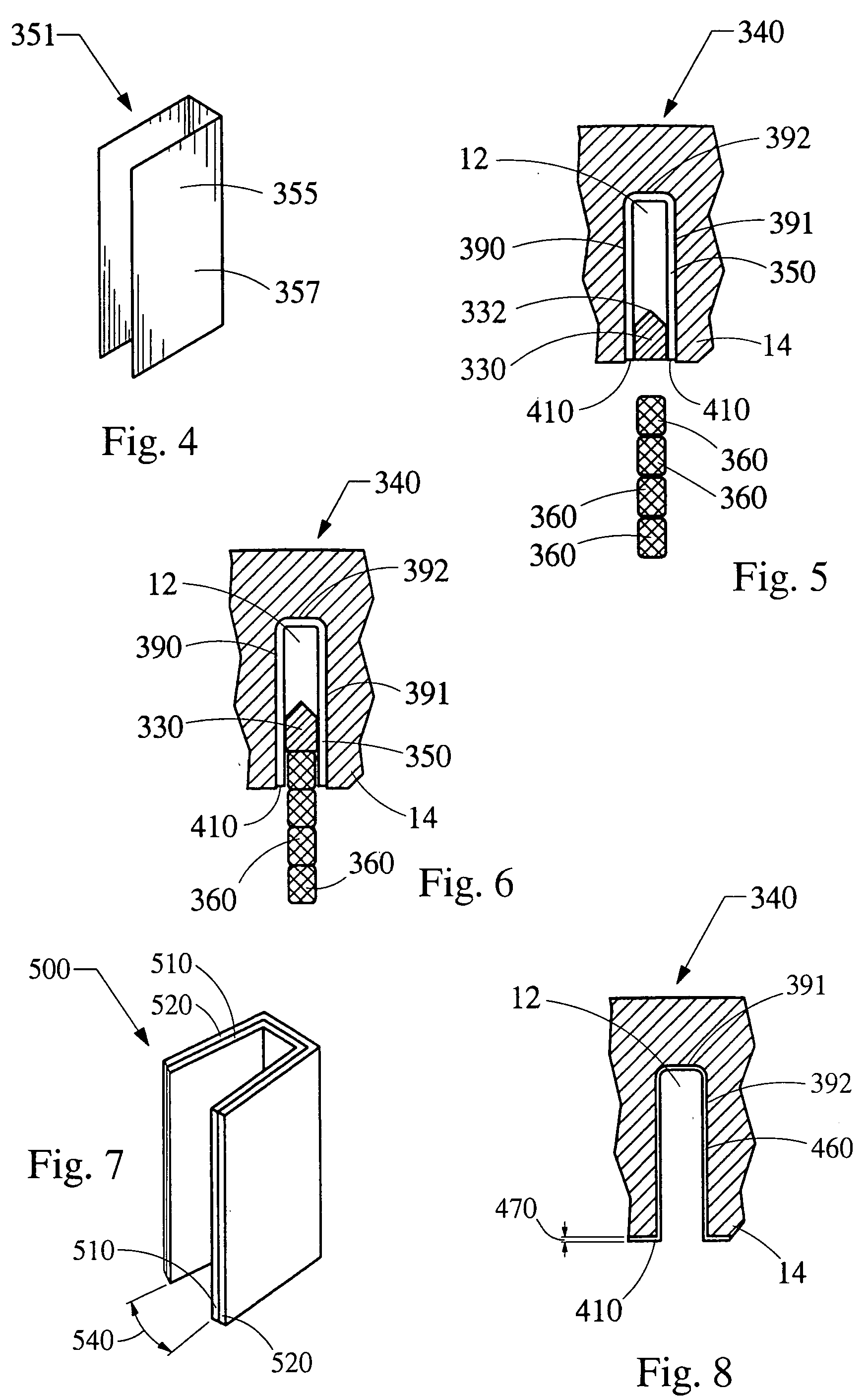
[0032] Now referring to FIG. 5, the present invention is shown as an insulated core slot 340 having tooling, indicated generally at 330, inserted into the insulated slots 340 prior to inserting the slot segments 360. The circumferential width of the tooling 330 preferably fits closely to the width of the insulated slot 340. To prevent the tooling 330 from catching the edges 310 of the insulator 350, similarly to the slot segments 360 catching the edges 310, the tooling 330 includes a point, indicated generally at 332, and is inserted in the radial direction 24 into the core slots 12.
[0033] Alternatively, the tooling 330 could include a point (not shown) on the axial end of the tooling 330, wherein the tooling 330 is inserted in the axial direction 16 into the core slots 12. In either case, radial point 332 or axial point (not shown), the point enters the core slots 12 prior to the rest of the tooling 330 which ensures that the edges 290 and 291 of the insulator 350 are not caught by...
third embodiment
[0036] Referring now to FIG. 7, a laminate, indicated generally at 500, of the present invention is shown. The laminate 500 is composed of at least two members, an insulator member, indicated generally at 510 and a spring member, indicated generally at 520 which are laminated or adhered together, typically by an adhesive applied in between the members 510 and 520. After assembly into a core slot 12, the insulator member 510 provides the necessary electrical isolation between the slot segments 360 and the core slots 12 and the spring member 520 provides a spring force, which secures the laminate 500 to the sides 390 and 391 of the core slots 12. The memory properties inherent to the properties of the spring member 520 cause the laminate 500, prior to insertion into a core slot 12, to have an angle, indicated generally at 540, between opposing sides of the laminate 500 to be greater than zero.
[0037] When the laminate 500 is inserted into a core slot 12, the sides 390 and 391 of the co...
fourth embodiment
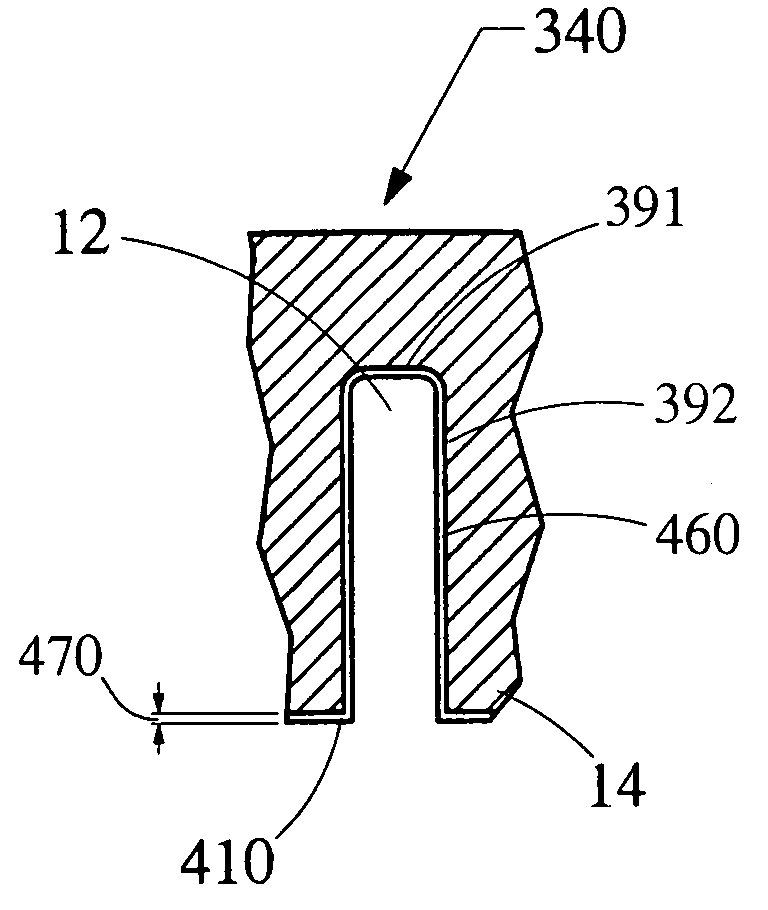
[0039] Referring now to FIG. 8, a fourth embodiment to the present invention is shown as an insulated core slot 340 wherein the insulation is composed of a coating, indicated generally at 460 having a very thin thickness, generally indicated at 470. The coating must be thin to allow for a high slot fill winding having minimum insulation in the core slots 12 and to prevent the buildup on the inner surface 14 of the core 10 which could potentially interfere with the spinning rotor which is located radially inward of the inner surface 14. The high slot fill stator assembly, by definition, has very thin insulation and therefore to be considered a high slot fill stator, the thickness 470 of the coating 460 must be less then 0.2 millimeter.
[0040] The cascaded winding for the stator is shown in FIGS. 9 through 9c. Each of the continuous conductors have a plurality of slot segments disposed in the core slots 12. The term continuous, utilized herein, refers to a conductor including end loops...
PUM
 Abstract
Description
Claims
Application Information
 - R&D
- Intellectual Property
- Life Sciences
- Materials
- Tech Scout
- Unparalleled Data Quality
- Higher Quality Content
- 60% Fewer Hallucinations
Browse by: Latest US Patents, China's latest patents, Technical Efficacy Thesaurus, Application Domain, Technology Topic, Popular Technical Reports.
© 2025 PatSnap. All rights reserved.Legal|Privacy policy|Modern Slavery Act Transparency Statement|Sitemap|About US| Contact US: help@patsnap.com


