Subsea actuator with magnetic return

a technology of subsea actuators and magnetic springs, which is applied in the direction of valve operating means/release devices, well accessories, and wellbore/well accessories, etc., can solve the problems of inability to produce high pressure large bore valves, excessively large springs, and long wired springs, etc., to achieve less spring force, no magnetic spring resistance, and small subsea actuator size

Inactive Publication Date: 2018-10-11
CHEVROU USA INC
View PDF11 Cites 2 Cited by
  • Summary
  • Abstract
  • Description
  • Claims
  • Application Information

AI Technical Summary

Benefits of technology

[0009]According to a second embodiment, a subsea actuator with magnetic return comprises the first embodiment but having a magnetic motor in lieu of the hydraulic piston, powered by an electric source. The subsea actuator with magnetic return is driven by the magnetic motor to move the valve stem in one linear direction, e.g., to open the subsea valve. Once the magnetic motor is turned off, the subsea actuator with magnetic return is moved to the opposite direction via a magnetic spring. The magnetic spring contains an array of magnets configured to create the required magnetic density and force to move the stem back to its initial position. The array of magnets is an arrangement of permanent magnets. The absence of any hydraulic actuator piston in this embodiment reduces the effects from hydrostatic head over the system motion, which in turn requires less spring force resulting in a smaller subsea actuator size.
[0010]According to a third embodiment, a subsea actuator with magnetic return comprises the second embodiment with a magnetic spring whose magnetic field can be turned on and off, or shield and unshield the magnetic force. The magnetic field of the magnetic spring can be turned off when the magnetic motor is turned on to move the valve stem in one linear direction, e.g., to open the subsea valve, so that no resistance from the magnetic spring occurs while the magnetic spring is compressed or extended. The magnetic field of the magnetic spring can be turned on when the magnetic motor is turned off to move the valve stem back to its initial position. In this embodiment, the magnetic spring is located on an actuator assembly where an electric current can be turned on and off, or shield and unshield the magnetic field. The ability to turn on and off the magnetic field of the magnetic spring will allow the reduction of the motor size. The magnetic spring can also be configured to autonomously return to its initial position via an uninterrupted power supply, e.g., a battery bank.
[0011]According to a fourth embodiment, a subsea actuator with magnetic return comprises a single magnetic spring powered by an electric source wherein variations of the current flow direction can make the single magnetic spring move in both directions. The subsea actuator with magnetic return is driven by the single magnetic spring which electric current applied in forward direction creates a magnetic field to move the stem in a linear stroke, e.g., to open the subsea valve. Once the electric current flow is applied to the single magnetic spring in the reversed direction, the single magnetic spring creates a magnetic field that moves the stem to the opposite side, e.g., to close the subsea valve. The adoption of a single bidirectional magnetic spring reduces the complexity of the subsea actuator resulting in a smaller subsea actuator design. The single magnetic spring can also be configured to autonomously return to its initial position via an uninterrupted power supply, e.g., a battery bank.
[0012]According to a fifth embodiment, a subsea actuator with magnetic return comprises the same described at first embodiment with a spring whose magnetic field can be turned on and off, or shield and unshield the magnetic force. The magnetic field can be turned off when the hydraulic pressure is applied on the piston to move the subsea actuator with magnetic return, so that no resistance from the spring occurs while the magnetic spring is compressed or extended. The magnetic field can be turned on when the hydraulic pressure is released to move the stem of the subsea valve back to its initial position. In this embodiment, the magnetic spring is located on an actuator assembly where an electric current can be turned on and off, or shield and unshield the magnetic field. The ability to turn the magnetic field on and off will allow the actuator piston area to be reduced. This reduction of the piston area in turn will require less spring force to overcome the hydrostatic head resulting in a small actuator size. The magnetic spring can also be configured to autonomously return to its initial position via an uninterrupted power supply, e.g., a battery bank.

Problems solved by technology

As the industry moves towards deeper waters, the higher sea bottom hydrostatic head requires the use of longer and bulkily wired springs which can be unfeasible to be produced for some high pressure large bore valves.
As a result of the longer springs, the actuators are more sensitive to its geometrical instabilities and have become more complex, heavier, and excessively large, driving subsea equipment to become exponentially larger.
These solutions have not been successful and have resulted in cracked springs, stem buckling, stem seal leakage, and seal extrusion.
The reliability problems introduced by these solutions exceed the benefit obtained by the reduction in actuator size.

Method used


Image

  • Subsea actuator with magnetic return
  • Subsea actuator with magnetic return
  • Subsea actuator with magnetic return

Examples


Embodiment Construction

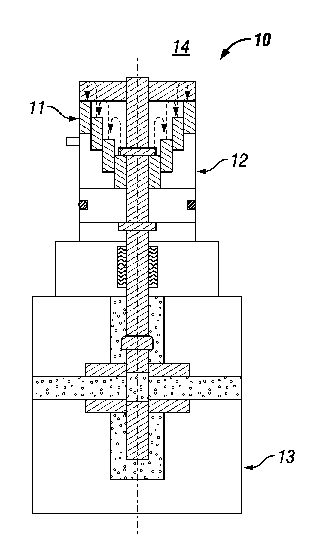
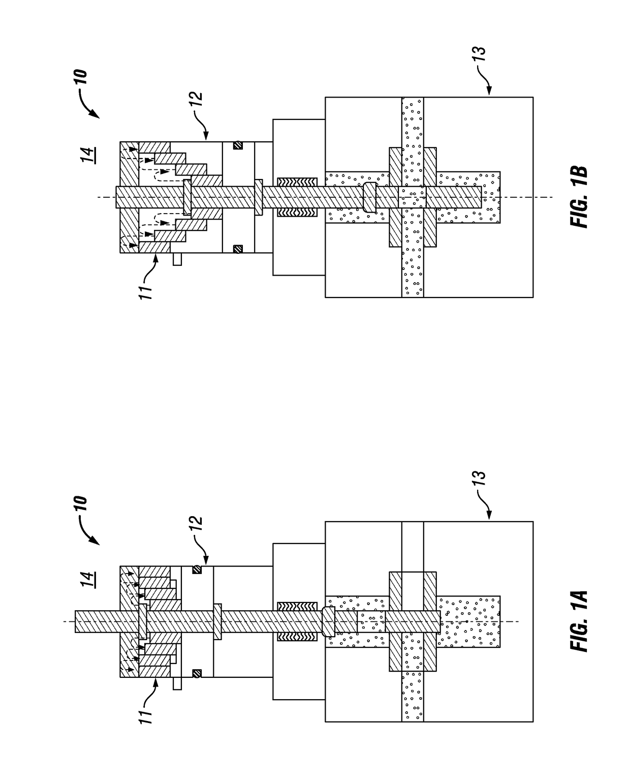
[0024]FIG. 1A illustrates an embodiment of a subsea actuator with magnetic return 10 comprising a hydraulic actuator piston 12 and a magnetic spring 11. In FIG. 1A, the subsea actuator with magnetic return 10 is in the initial position (valve closed). FIG. 1B illustrates an embodiment of a subsea actuator with magnetic return 10 comprising a hydraulic actuator piston 12 and a magnetic spring 11. In FIG. 1B, the subsea actuator with magnetic return is in the stroked position (valve open). The subsea actuator with magnetic return 10 can be assembled to a subsea valve 13. The subsea actuator with magnetic return 10 is powered by hydraulic force to move the valve stem 14 in one direction, e.g., to open the subsea valve as shown in FIG. 1B. The subsea actuator with magnetic return 10 is moved in the opposite direction via a magnetic spring 11 as shown in FIG. 1A. The magnetic spring 11 contains an array of magnets configured to create the required magnetic density and force to move the v...


PUM


Abstract

The present invention is directed to a subsea actuator with magnetic return. The subsea actuator with magnetic return is assembled to a subsea valve. The subsea actuator with magnetic return allows subsea actuators to be designed with increased reliability and a reduction in size. The reduction in size also provides opportunities to reduce the size of the topsides hardware that supports the subsea valve function.

Description

CROSS-REFERENCE TO RELATED APPLICATION[0001]The present application claims the benefit of U.S. Provisional application Ser. No. 62 / 481,878 filed on Apr. 5, 2017, entitled “Subsea Actuator With Magnetic Return”, the contents of which are incorporated herein by reference in its entirety.FIELD OF THE INVENTION[0002]This invention related to a subsea actuator. In particular, this invention relates to a subsea actuator with a magnetic return.BACKGROUND OF THE INVENTION[0003]Subsea valves are used in a variety of subsea applications in the oil and gas industry at a variety of depths. For example, subsea valves are used as under water safety valves in subsea trees and safety valves in production risers, or as a flow control device in manifolds, flowline connection frames and pipeline structures.[0004]Currently subsea valves are typically equipped with an actuator that moves the valve stem in one direction via a means of motion such as a hydraulic piston. The linear motion of the hydraulic ...

Claims


Application Information

Patent Timeline
Patent Type & Authority Applications(United States)
IPC IPC(8): E21B34/06F16K31/06
CPCE21B34/066F16K31/0644F16K31/084F16K31/1221F16K3/0254E21B34/04
Inventor PAULO, PAULO CEZAR SILVA
Owner CHEVROU USA INC
Why Eureka
Try Eureka