Printing position alignment method and printing apparatus

a printing apparatus and position alignment technology, applied in printing mechanisms, spacing mechanisms, printing, etc., can solve problems such as deterioration of print quality, and possible misalignment of dot printing positions, so as to reduce the impact of external disturbance, the effect of effective alignmen

Inactive Publication Date: 2010-09-07
CANON KK
View PDF13 Cites 16 Cited by
  • Summary
  • Abstract
  • Description
  • Claims
  • Application Information

AI Technical Summary

Benefits of technology

[0014]An object of the invention is to enable an effective and automatic registration process which uses only a small amount of resources such as ink and printing media, while reducing an impact of an external disturbance.
[0020]In the invention, it is determined whether from data of optical characteristics of respective alignment patterns, the data are influenced by a disturbance. When the influence of the disturbance is small so that the data are reliable, a piece of data in which a misalignment of a relative printing position of the second alignment pattern elements to the first alignment pattern elements is smallest and data of optical characteristics in the neighborhood of the piece of data are used so that an adjusting value is calculated. In such a range, a change of density to relative shifting amount of printing position is obtained as a simple function so that an adjusting value can be determined with high accuracy. Meanwhile, when the influence of the disturbance is large, a range of an amount of shifting of a relative position is made wider than that in the case where the influence of the disturbance is small, a large number of pieces of data of optical characteristics are used. Thus, since a change of optical characteristics (density) becomes large, a ratio of the disturbance to a density curve is reduced, and an increase of the number of pieces of data to be used is capable of improving the reliability of an adjusting value.
[0021]As described above, in accordance with the invention, when performing an automatic registration process, it becomes possible to improve the efficiency of the process and reduce an amount of resource such as ink and printing media as much as possible, with the influence of a disturbance being reduced.

Problems solved by technology

Further, also in a case of use of multiple print heads, a misalignment of dot printing positions may occur due to a relative position displacement among the print heads.
In addition, even the same ejection openings may cause a misalignment between dot printing positions when performing printing (bi-directional printing) by reciprocal movement of the print head in both directions.
When the misalignments of these dot printing positions occur as described above, print quality is deteriorated.
However, this method forces a user to perform a complex operation of a visual judgment or a selection setting.
In particular, in the case of an ink whose optical characteristic of alignment patterns is originally difficult to detect, like the light color ink described above, the optical sensor can only output data with a low S / N ratio, so that such ink is particularly susceptible to an influence of the external disturbance.
However, these countermeasures are not desirable in terms of cost and usability.
Therefore, there are problems left that the performing of a registration process needs a long time; the printing of the pattern for abnormal detection accordingly increases an amount of ink to be consumed, and in some cases, increases an amount of printing media, i.e., requires more resources to be consumed.

Method used


Image

  • Printing position alignment method and printing apparatus
  • Printing position alignment method and printing apparatus
  • Printing position alignment method and printing apparatus

Examples


second embodiment

[0090]Next, other embodiment to which the reliability determination is applied is described.

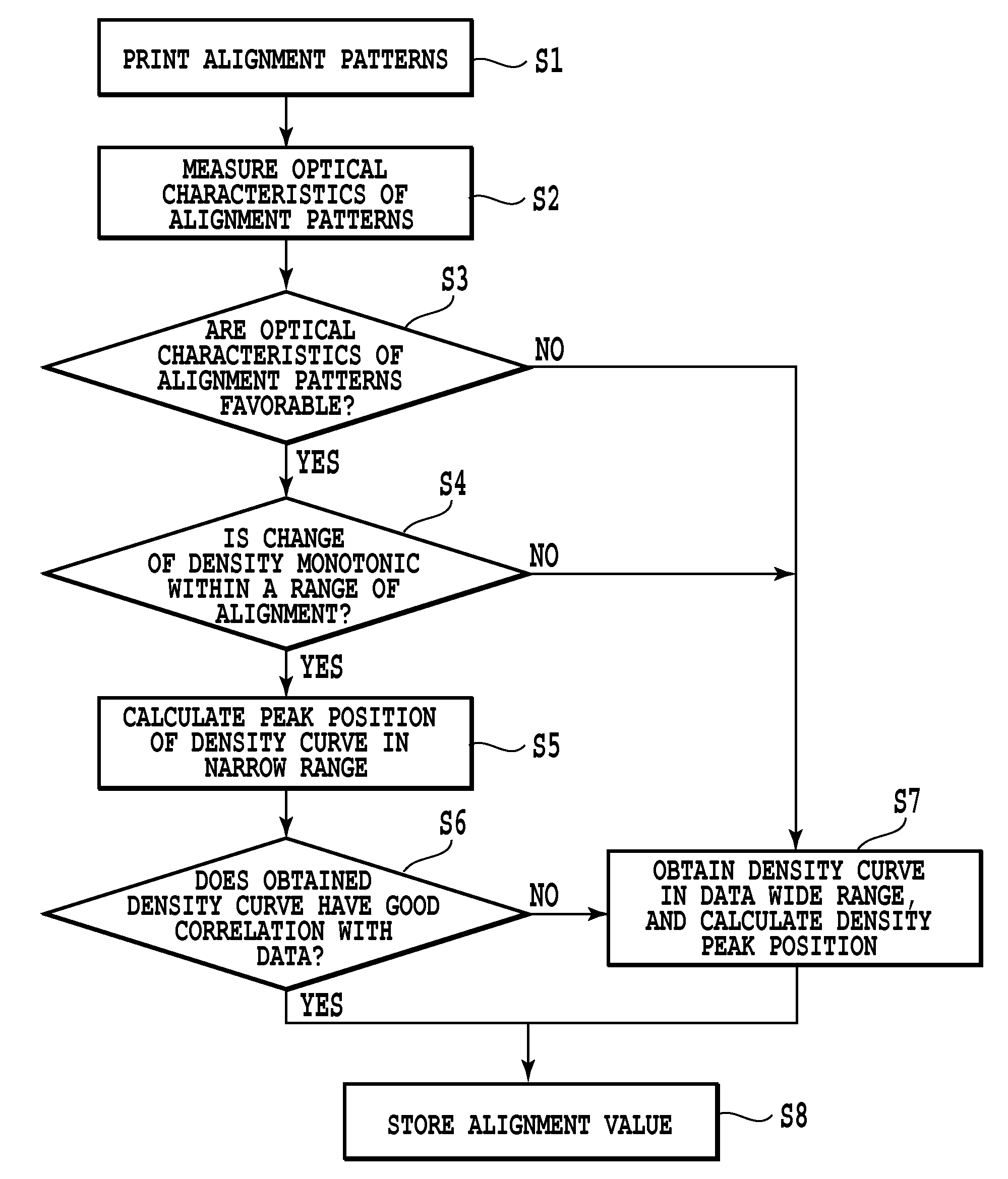
[0091]FIG. 9 shows procedures of processes of the determining reliability and the obtaining of an adjusting value in a second embodiment of the invention. In this embodiment, two groups of alignment patterns can be printed, and a second group of alignment patterns is printed in accordance with the reliability of data of a first group of alignment patterns. The first group of alignment patterns is for a coarse alignment satisfying an alignment range required for a mechanical tolerance of a printing apparatus. Meanwhile, the second group of alignment patterns, a unit of shifting of a relative printing position between alignment pattern elements is set smaller than that for the first group of alignment patterns so as to have a high accuracy of an alignment. In the first embodiment, as a result of a reliability determination, when the obtaining of an adjusting value with high accuracy and with le...


PUM


Abstract

Multiple alignment patterns, each composed of first and second alignment pattern elements printed by forward and backward movements of a print head, respectively, are formed while the relative printing positions of the two elements are shifted. From optical characteristics data thereof, whether the data is influenced by a disturbance is determined. When the data is determined to be less influenced by the disturbance and therefore to be reliable, an adjusting value for aligning positions in printing in reciprocal movements is calculated by use of: data with the smallest relative printing position misalignment between the first and second alignment pattern elements; and data of optical characteristics close to the data. When the data is largely influence by the disturbance, a range of shifting of relative position is widened than that of the data less influenced by the disturbance so that more data pieces are used to obtain the adjusting value.

Description

BACKGROUND OF THE INVENTION[0001]1. Field of the Invention[0002]The present invention relates to a printing position alignment method in dot matrix printing, and a printing apparatus using the method.[0003]2. Description of the Related Art[0004]One type of printing apparatuses performing printing by forming dots on a printing medium uses a print head that moves in a predetermined direction relative to a printing medium and has, as printing elements, ink ejection openings arranged in a direction (e.g., in a direction in which a printing medium is conveyed) different from the predetermined direction. Nowadays, as for such a printing apparatus (an inkjet printing apparatus), there is a trend of increasing the number of ejection openings arranged in a print head to achieve a higher printing speed. Furthermore, increasingly widely used is a print head provided with multiple arrays of ejection openings corresponding to multiple ink colors so as to perform color printing. Particularly, the...

Claims


Application Information

Patent Timeline
Patent Type & Authority Patents(United States)
IPC IPC(8): B41J29/393
CPCB41J2/2135B41J29/393B41J19/145
Inventor TOMIDA, AKIHIROKAKINUMA, AKIHIROKANEMATSU, DAIGOROBABA, NAOKONAGAMURA, MITSUTOSHIWATANABE, ASAKOHASHIMOTO, REIJINAKAJIMA, YOSHINORI
Owner CANON KK
Why Eureka
Try Eureka