Slide lock fastener

a slide lock and fastener technology, applied in the direction of fastening means, screws, dowels, etc., can solve the problems of easy disassembly of the pin, damage to the fastener, added step and additional expense, etc., and achieve the effect of quick fastening and unfastening

Inactive Publication Date: 2010-09-07
MANN HUMMEL GMBH
View PDF11 Cites 9 Cited by
  • Summary
  • Abstract
  • Description
  • Claims
  • Application Information

AI Technical Summary

Benefits of technology

[0012]The slide lock fastener for mounting components, particularly an air filter housing or an intake pipe, is advantageously further developed according to the invention in that it is readily fastened and unfastened. In the fastened state, the slider member is inserted between the head of the locking pin and one surface of a first part to be fastened. By sliding the slider member between the head of the locking pin and a part to be fastened, the locking pin is displaced in an axial direction such that the sleeve wall deforms and engages a surface of a second part to be fastened. Thus, pressure is exerted on opposite sides of the first and second parts thereby creating an attached condition between the parts. According to one embodiment, the head of the locking pin rests in a recessed region formed in the top surface of the slider member, thereby maintaining the slide lock fastener in the fastened state.

Problems solved by technology

Furthermore, once a pin is inserted into the receiving portion of a grommet, the pin is not readily removable without likely causing damage to the fastener (e.g., damaging the grommet).
Finally, the fastener illustrated in FIG. 1 involves the added step and the added expense of forming a threaded hole in the plate member in order to fixedly mount the pin thereto.

Method used


Image

  • Slide lock fastener
  • Slide lock fastener
  • Slide lock fastener

Examples


Embodiment Construction

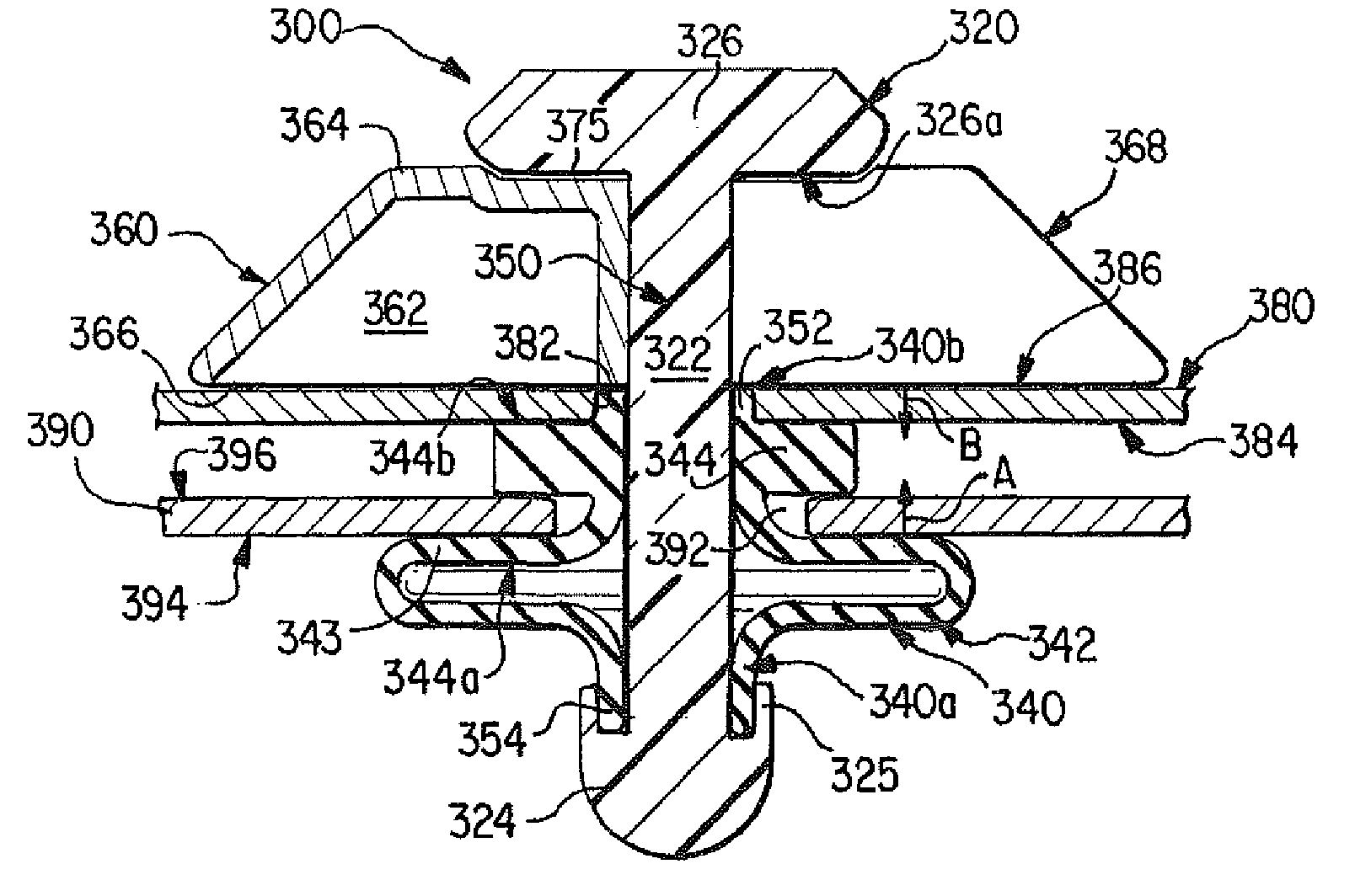
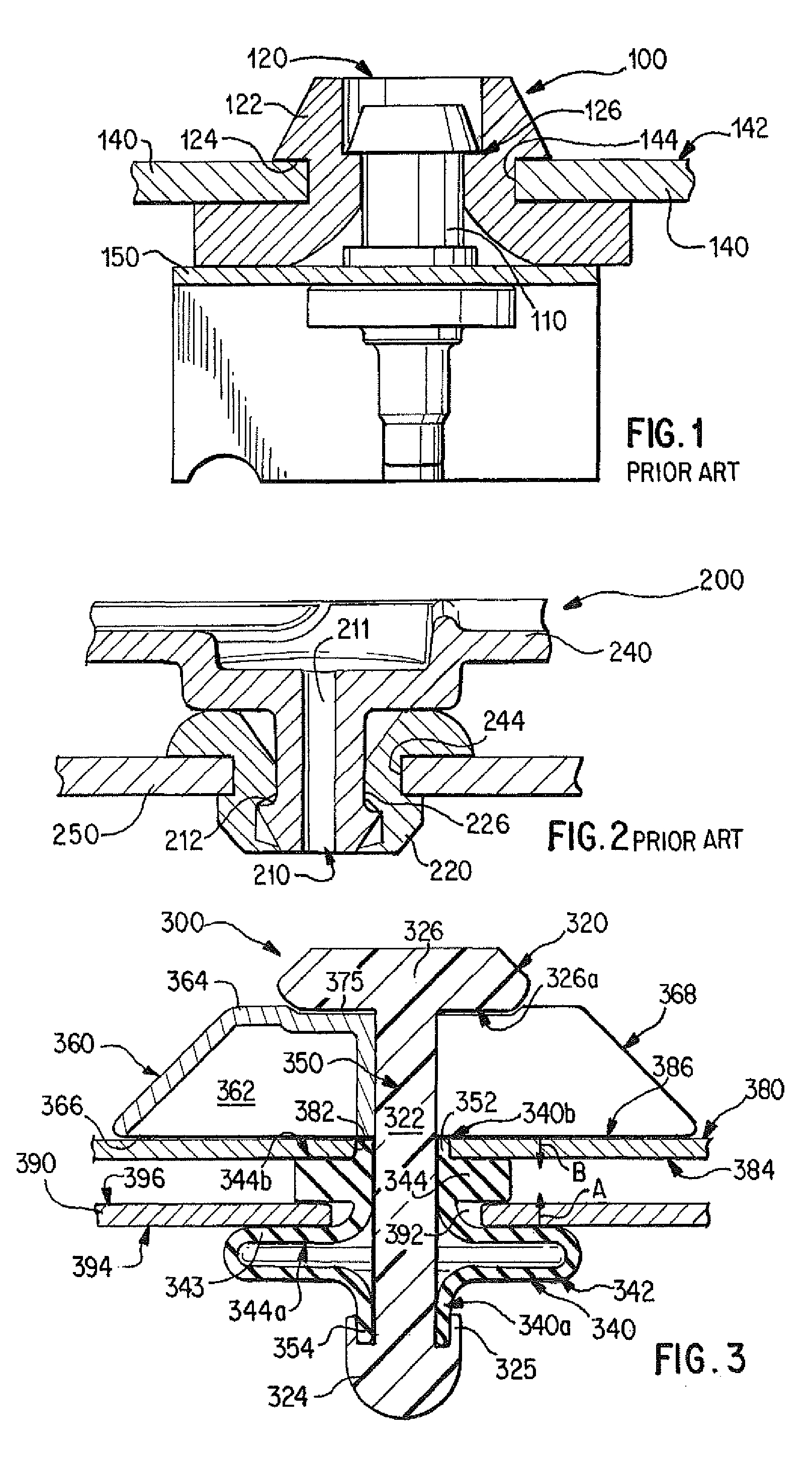
[0020]A cross sectional illustration of an assembled slide lock fastener according to one embodiment is shown in FIG. 3. The slide lock fastener 300 includes a locking pin 320, a cylindrical isolation sleeve 340, and a slider member 360, which cooperate to fasten together two or more components. Such components include an air filter housing, an intake pipe, and a fixed frame member. For example, shown in FIG. 3 are wall sections 380 and 390 of an air filter housing and a fixed frame member, respectively.

[0021]The locking pin 320 includes an elongated shaft portion 322 having a pin head 326 at one end of the shaft and, in its assembled state, a retaining member 324 attached at the opposite end. The retaining member 324, which can be attached to the shaft portion via a snap-on connection, a screw-on connection, or using some other suitable connection, comprises a retaining shoulder 325. As described in additional detail below, the retaining shoulder is adapted to retain one end 354 of...


PUM


Abstract

A slide lock fastener assembly for removeably fastening a first part to a second part, in which the fastening and unfastening operations include a sliding operation, the fastener assembly having a locking pin, a cylindrical isolation sleeve, and a slider member. A fastened condition is created between the two parts by inserting the slider member between a surface of the first part and a locking pin head of the locking pin. The insertion causes a deformation of a wall portion of the isolation sleeve such that a portion of the wall engages a surface of the second part.

Description

BACKGROUND OF THE INVENTION[0001]This invention relates to a releasable fastener. The fastener of the invention is particularly useful to mount components to a plate member such as a piece of sheet metal in the engine compartment of a motor vehicle.[0002]Conventional fasteners for attaching a component to a plate member are shown in FIGS. 1 and 2. In FIG. 1, fastener 100 includes a pin 110 and an isolation grommet 120 that cooperate to fasten component 140 to plate member 150. Pin 110 is fixedly mounted to the plate member 150 via a threaded hole formed in the plate member. The pin includes a pin main body 111 having a protruding flange 112 at a head portion 113 thereof. Grommet 120, which is inserted into a mounting aperture 144 formed in a wall of the component 140, includes cylinder member 122 having an exterior flange 124 for engaging a surface 142 of the component, and an interior peripheral surface 126 for engaging the flange 112 of the pin. The head of the pin 110 is inserted...

Claims


Application Information

Patent Timeline
Patent Type & Authority Patents(United States)
IPC IPC(8): F16B13/06
CPCF16B19/1072F16B19/109
Inventor KIDMAN, BEAU
Owner MANN HUMMEL GMBH
Why Eureka
Try Eureka