
Card edge connector with an improved latch

a card edge connector and latch technology, applied in the direction of coupling device connection, coupling/disconnecting parts engagement/disengagement, printed circuits, etc., can solve the problem of occupying too much space of electronic devices

Active Publication Date: 2010-09-07
HON HAI PRECISION IND CO LTD
View PDF6 Cites 28 Cited by
  • Summary
  • Abstract
  • Description
  • Claims
  • Application Information

AI Technical Summary

Benefits of technology

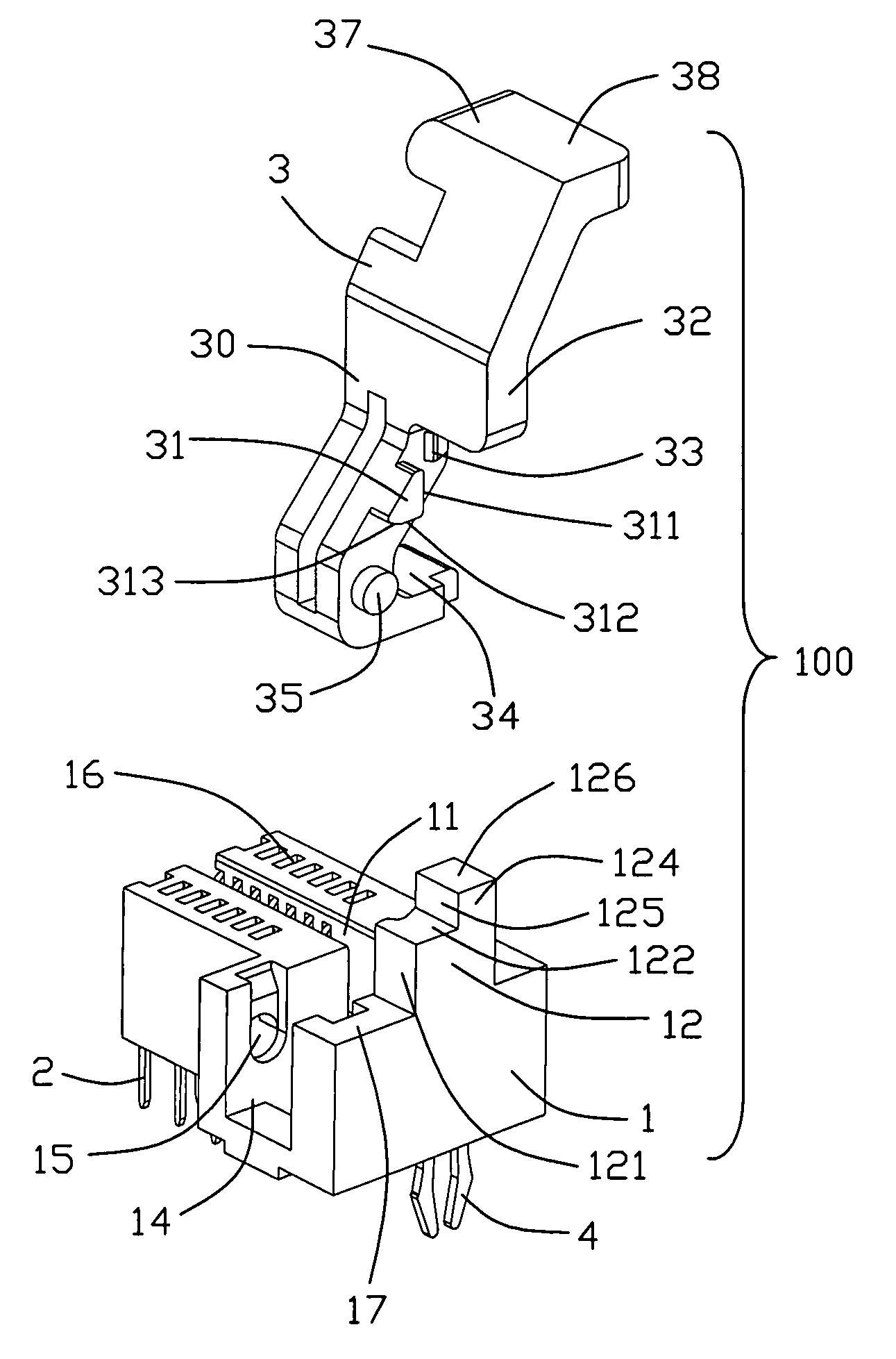
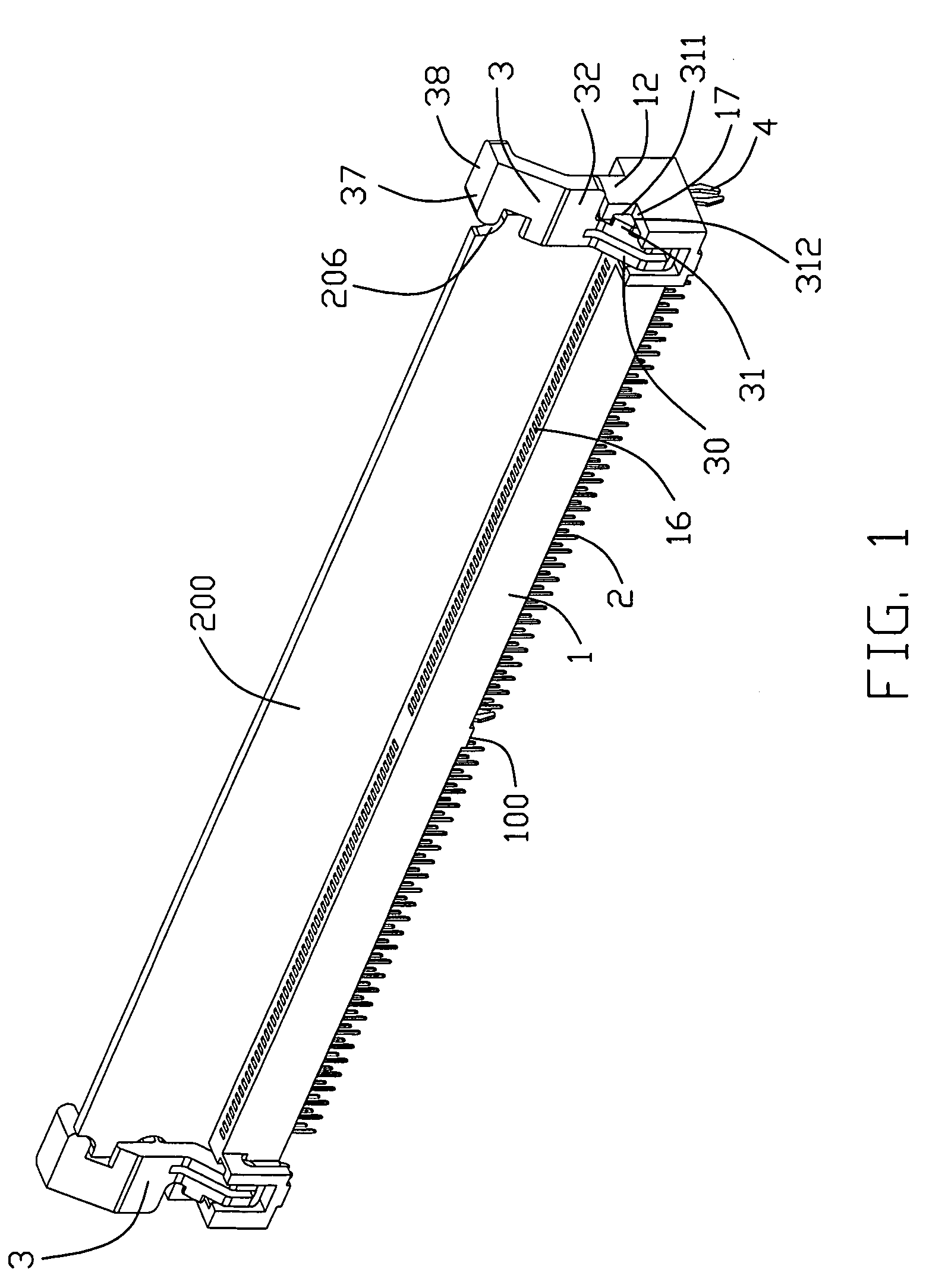
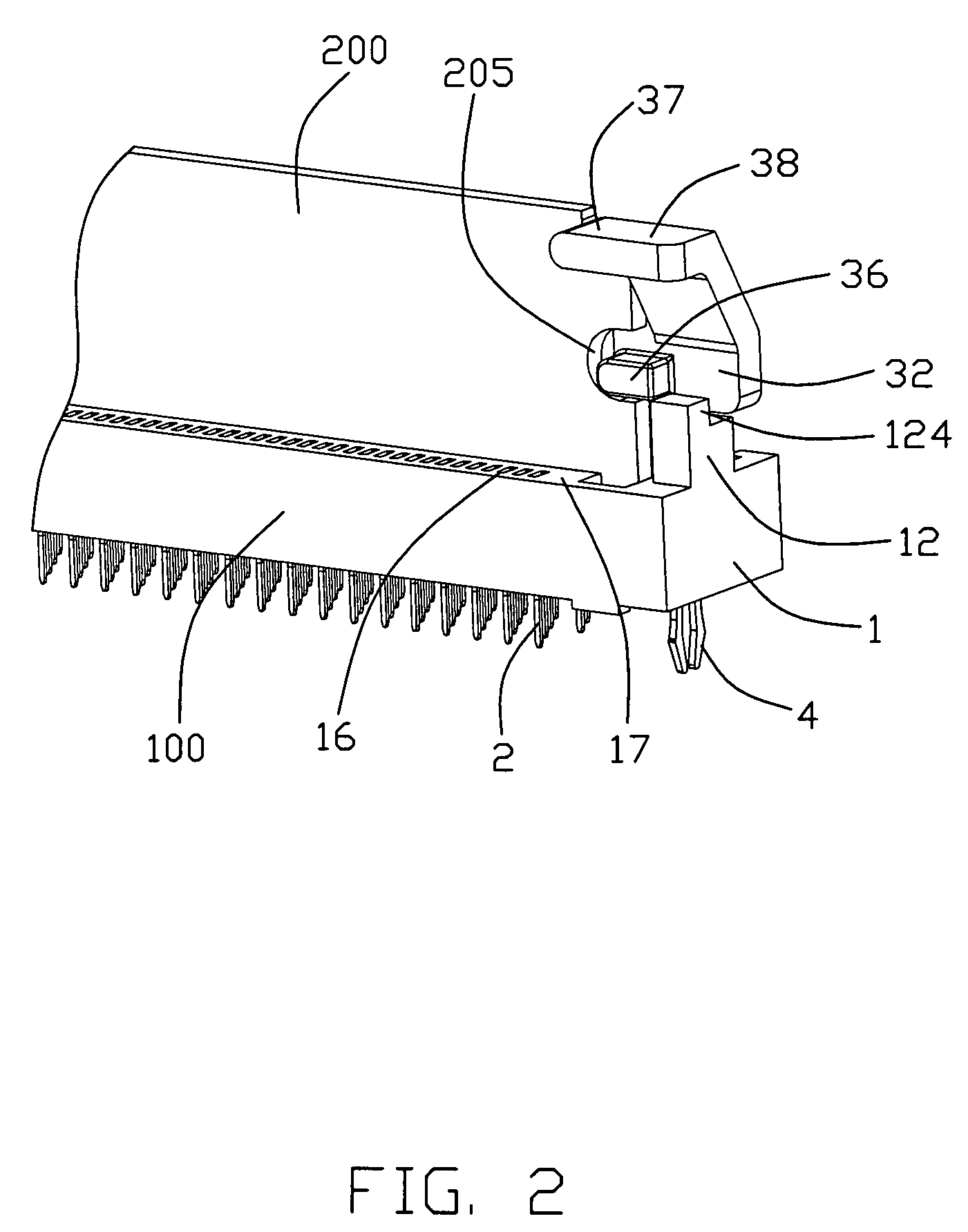
[0007]According one aspect of the present invention, a card edge connector for receiving a module comprises an elongated insulative housing having a pair of elongated side walls, a central slot extending therebetween for insertion of the module, and a receiving slot formed on one of the side walls and communicating with the central slot. A plurality of terminals are positioned in the side walls and extend into the central slot thereof. A latch is rotatably received in the receiving slot for locking the module in the insulative housing at a first position and for ejecting the module out of the insulative housing at a second position. The latch has a main body and a stopping device projecting from the main body to engage with an upper surface of the insulative housing when the latch is at the first and second position, thereby preventing the latch from over-rotating beyond the first and second positions.

Problems solved by technology

The latches which are rotated along the lengthwise direction of the insulative housing will occupy too much space of the electronic device in the lengthwise direction.

Method used


Image

  • Card edge connector with an improved latch
  • Card edge connector with an improved latch
  • Card edge connector with an improved latch

Examples


Embodiment Construction

[0017]Reference will now be made to the drawing figures to describe the preferred embodiment of the present invention in detail.

[0018]Referring to FIGS. 1-2, the card edge connector 100 according to the present invention used for receiving a memory module 200, comprises an elongated insulative housing 1, a plurality of terminals 2 mounted on the insulative housing 1, a pair of board locks 4 disposed in the insulative housing 1 and a pair of latches 3 rotatably attached to the insulative housing 1.

[0019]Referring to FIGS. 1, 3 and 4, the insulative housing 1 has a pair of elongated side walls formed with a plurality of channels 16 for receiving the terminals 2, a central slot 11 extending therebetween for receiving the memory module 200 and a pair of receiving slots 14 formed on one of the side walls and communicating with the central slot 11. The terminals 2 extend into the central slot 11 for electrically and mechanically engaging with the memory module 200. The receiving slots 14 ...


PUM


Abstract

A card edge connector (100) for receiving a module (200) includes an elongated insulative housing (1) having a pair of elongated side walls, a central slot (11) extending therebetween for insertion of the module, and a receiving slot (14) formed on one of the side walls and communicating with the central slot. A group of terminals (2) are positioned in the side walls and extend into the central slot thereof. A latch (3) is rotatably received in the receiving slot for locking the module in the insulative housing at a first position and for ejecting the module out of the insulative housing at a second position. The latch has a main body (30) and a stopping device (31) projecting from the main body to engage with an upper surface (17) of the insulative housing when the latch is at the first and second position, thereby preventing the latch from over-rotating beyond the first and second positions.

Description

BACKGROUND OF THE INVENTION[0001]1. Field of the Invention[0002]The present invention generally relates to a card edge connector for receiving a module and more particularly to a card edge connector having a latch for removing the module from the card edge connector.[0003]2. Description of Related Art[0004]A conventional card edge connector is fixed in an electronic device such as a computer for receiving a memory module. Such connector is mounted on a printed circuit board (PCB), and comprises an elongated insulative housing, a plurality of terminals received therein and a pair of latches attached thereto. The insulative housing has a central slot extending along its lengthwise direction for receiving the memory module. The insulative housing has a pair of towers integrally formed on two opposite ends thereof. Each tower has a receiving slot. The latches which are rotatably received in the receiving slot could be rotated inwardly for locking the memory module in the insulative hous...

Claims


Application Information

Patent Timeline
Patent Type & Authority Patents(United States)
IPC IPC(8): H01R12/18H01R12/71
CPCH01R12/7005H01R12/721
Inventor GUAN, HAI-FEIBU, XUE-WULIU, TING-SHUN
Owner HON HAI PRECISION IND CO LTD
Learn More