High wind elevation mechanism for a satellite antenna system

a satellite antenna and high-wind technology, applied in the direction of antenna details, antenna adaptation in movable bodies, antennas, etc., can solve the problems that the elevation mechanism cannot raise and lower the dish, and achieve the effect of stable support for the dish, improved resolution, and longer strokes

Inactive Publication Date: 2010-09-07
WINEGARD
View PDF32 Cites 13 Cited by
  • Summary
  • Abstract
  • Description
  • Claims
  • Application Information

AI Technical Summary

Benefits of technology

[0009]In operation, the linear actuator can be moved between extended and retracted positions to cause the dish to move between its stowed and deployed positions. In the stowed position, the dish faces downwardly and in a deployed position, the dish faces upwardly of the horizon at the targeted satellite. The linear actuator has a longer stroke than in prior designs which allows for finer control of the deployed position of the dish for improved resolution. Additionally, the overall configuration of the elevation mechanism provides a very strong arrangement for moving the dish between its stowed and deployed positions including in adverse conditions of high winds and snow and provides a very stable support for the dish in all of its positions even under such adverse conditions.

Problems solved by technology

Otherwise, the elevation mechanism may not be able to raise and lower the dish in adverse conditions or maintain it in a stable deployed position targeted on the satellite to receive and / or send signals.

Method used


Image

  • High wind elevation mechanism for a satellite antenna system
  • High wind elevation mechanism for a satellite antenna system
  • High wind elevation mechanism for a satellite antenna system

Examples


Embodiment Construction

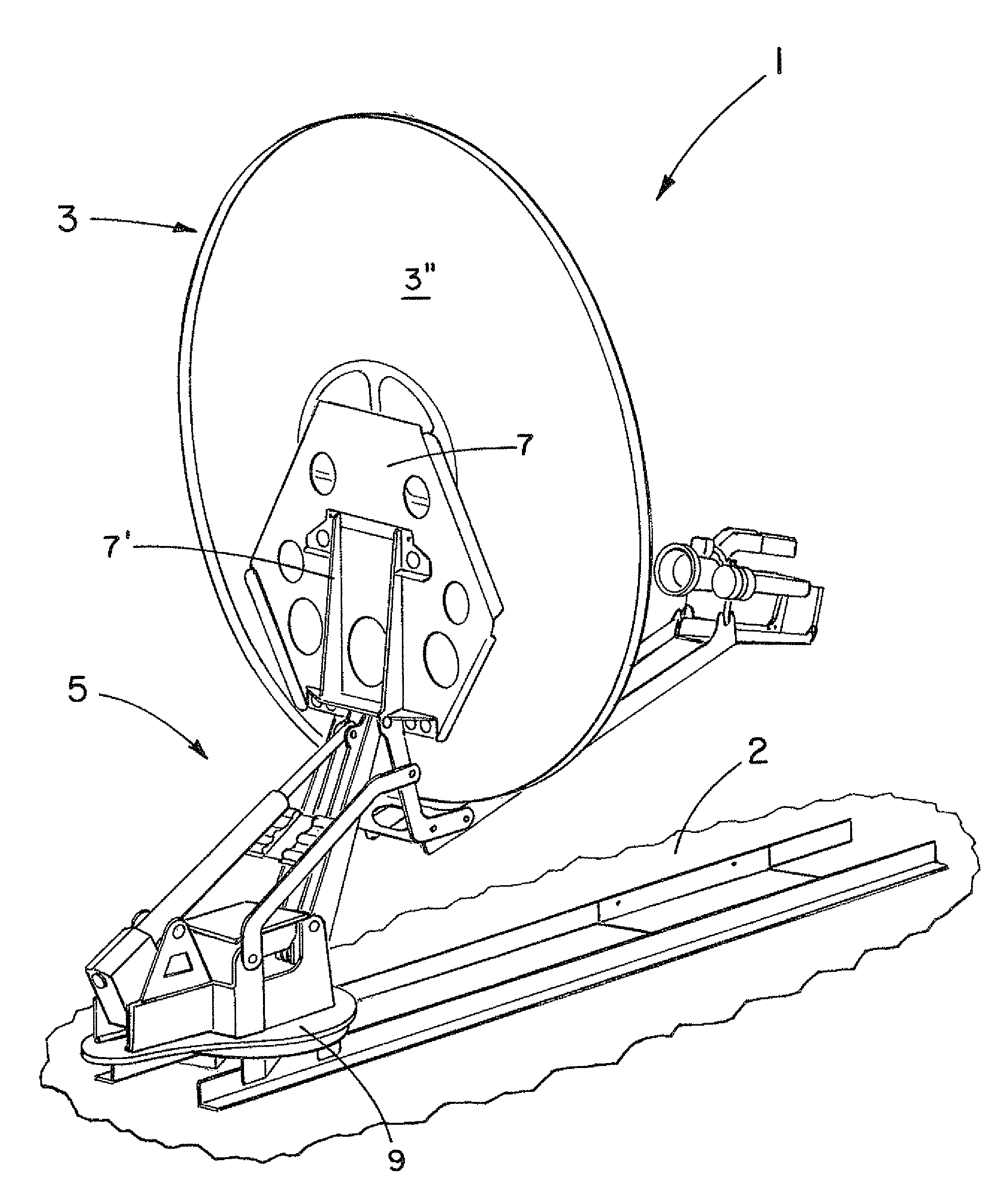
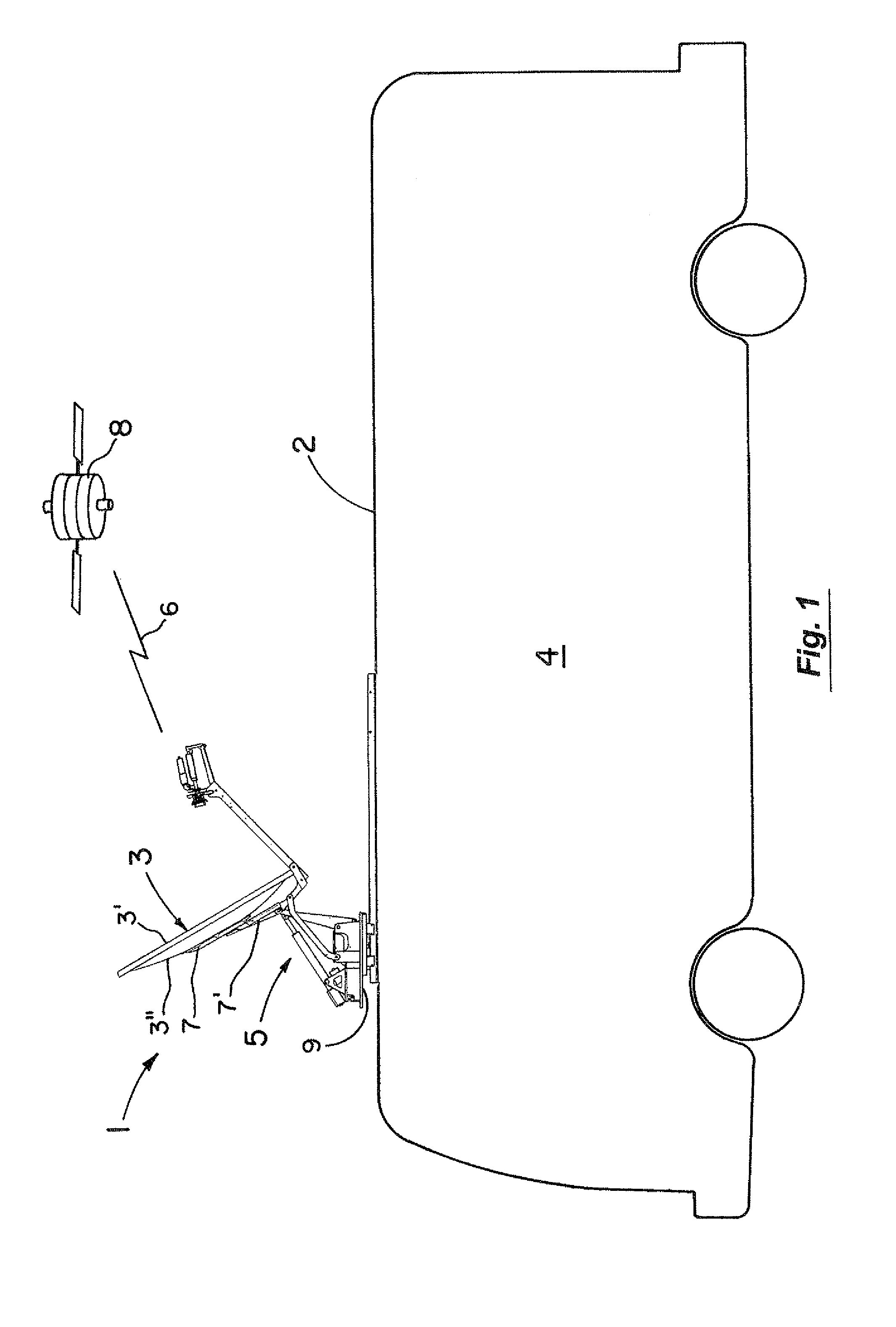
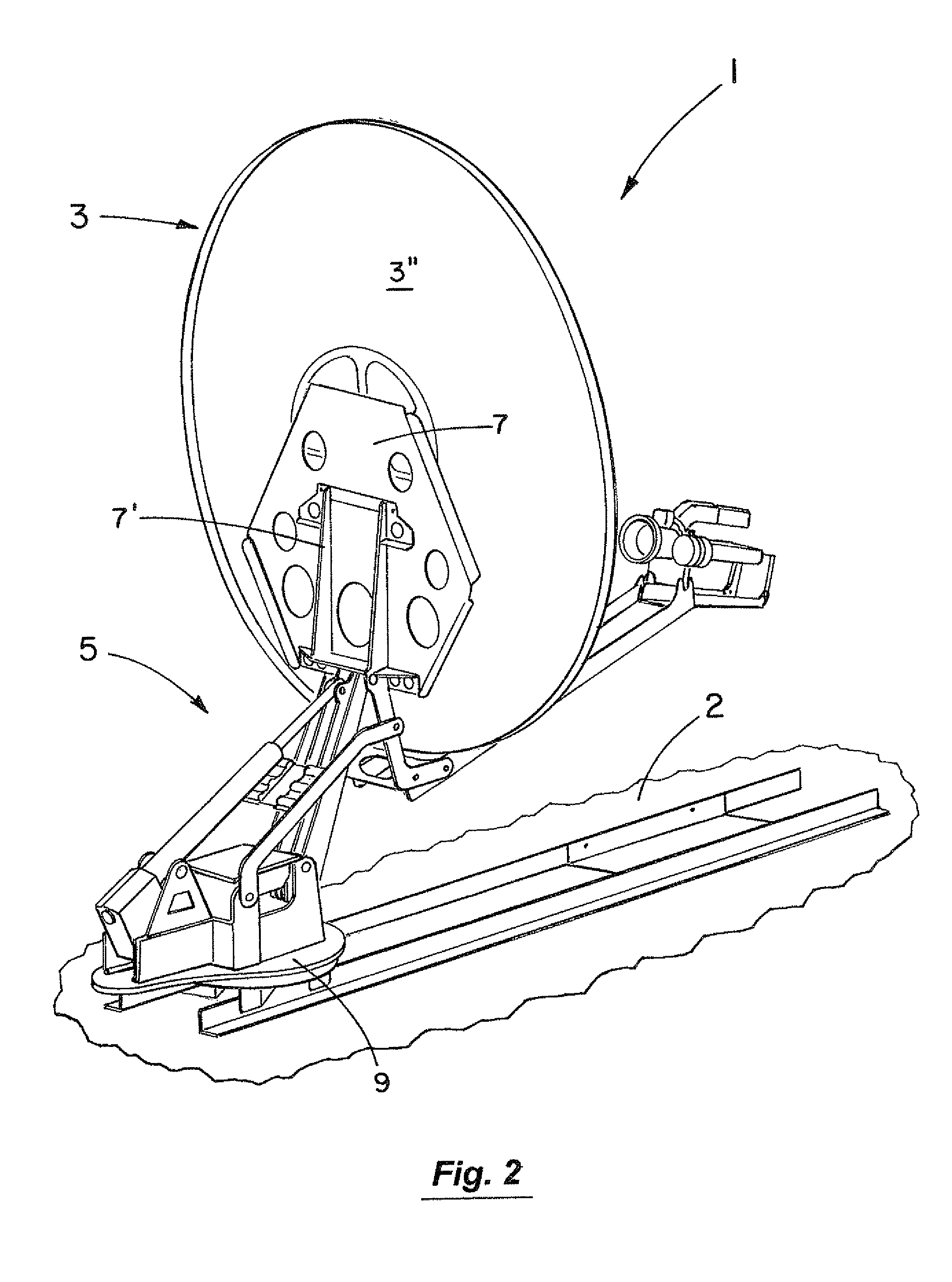
[0017]FIGS. 1 and 2 illustrate the satellite system 1 of the present invention with the dish member 3 in a raised or deployed position atop the roof 2 of a recreation vehicle 4. The dish member 3 in this regard is targeted in FIG. 1 to communicate (receive and / or send signals 6) with the satellite 8. In FIG. 3, the dish member 3 is shown in a lowered or stowed position substantially flush against the vehicle roof 2. The controls for the positioning of the satellite system 1 (e.g., azimuth, elevation, deployed, and stowed) are preferably motorized and operated remotely from within the vehicle 4 in a conventional manner.

[0018]In operation as illustrated in the series of FIGS. 4-6 (with the main body of the dish member 3 shown) and in the companion series of FIGS. 4a-6a (with the main body of the dish member 3 removed for clarity), the satellite system 1 includes the elevation mechanism 5. The elevation mechanism 5 is designed to selectively raise and lower the dish member 3. The dish ...


PUM


Abstract

An elevation mechanism for a satellite antenna system. The elevation mechanism includes tilt links or arms, lift links, and a linear actuator with an adjustable length leg arrangement. Each tilt arm is pivotally mounted at its inner and outer end portions to the base or azimuth plate of the system and to the back of the dish of the system. Similarly, each lift link is pivotally mounted at its inner and outer end portions to the base and to the back of the dish. The linear actuator in turn is pivotally mounted at its inner end portion to the base and at its outer end portion to the lift links. In operation, the linear actuator can be moved between extended and retracted positions to cause the dish to move between its stowed position facing downwardly and a deployed position facing upwardly of the horizon at a targeted satellite.

Description

RELATED APPLICATION[0001]This application claims the benefit of U.S. Provisional Patent Application Ser. No. 60 / 911,780 filed Apr. 13, 2007, which application is incorporated herein by reference.BACKGROUND OF THE INVENTION[0002]1. Field of the Invention[0003]This invention relates to the field of satellite antenna systems in which the dish of the system can be easily and quickly elevated from a stowed position facing downwardly to a deployed position targeted on a satellite.[0004]2. Discussion of the Background[0005]Satellite antenna systems mounted on recreational or similar vehicles or otherwise intended for use outdoors need to have elevation mechanisms that can easily and quickly move the dish of the system between stowed and deployed positions. In the stowed position, the dish preferably faces downwardly for protection from the elements including wind and snow. In the deployed position, the dish is typically directed upwardly (e.g., at 40-45 degrees from the horizon) toward a s...

Claims


Application Information

Patent Timeline
Patent Type & Authority Patents(United States)
IPC IPC(8): H01Q3/12
CPCH01Q1/1214H01Q1/1235H01Q1/125H01Q1/32
Inventor CONRAD, TIMOTHY J.
Owner WINEGARD
Why Eureka
Try Eureka