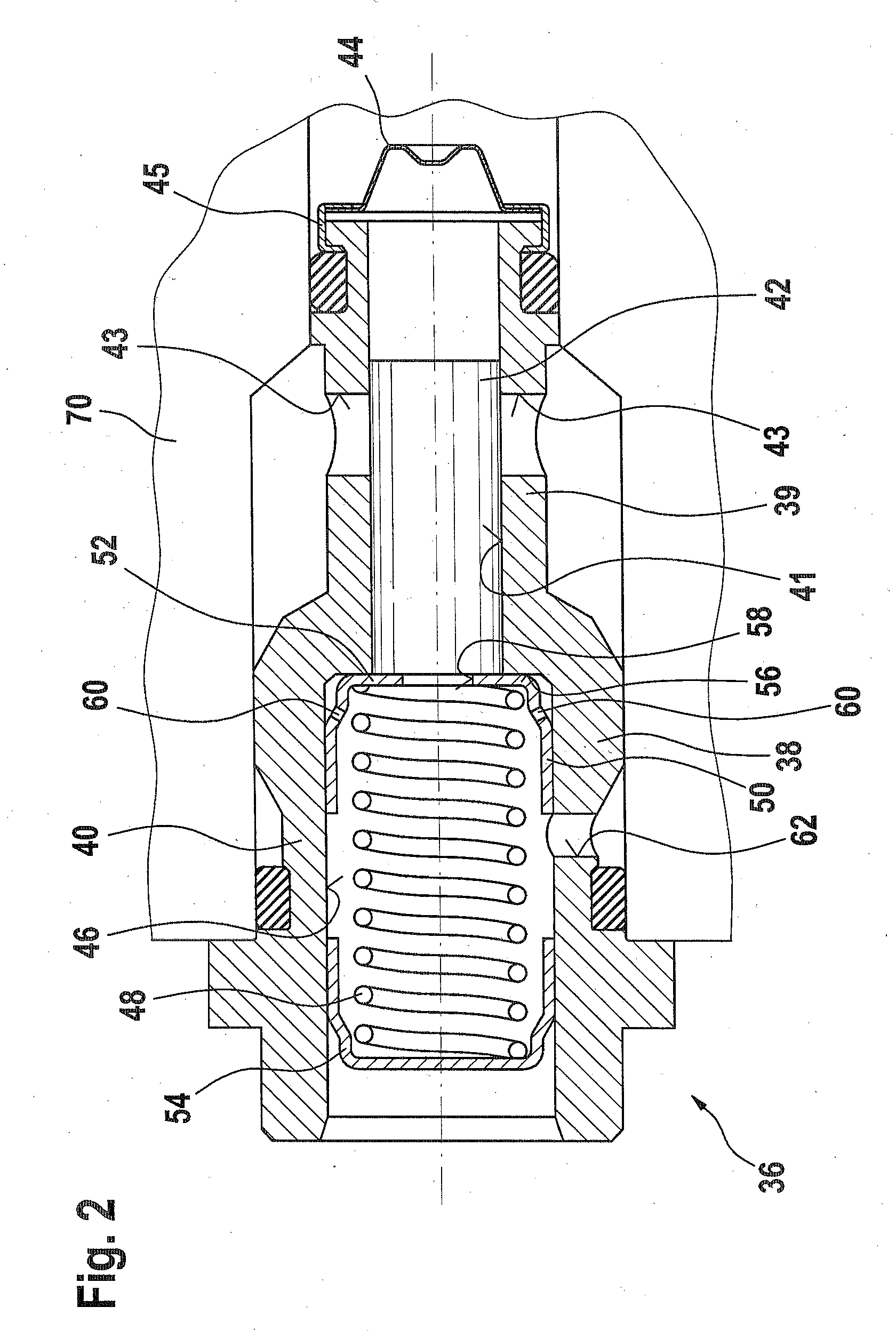
[0003]The fuel overflow valve according to the invention having the characteristics of claim 1 has the
advantage over the prior art that the valve member, independently of the valve spring, can execute a longer stroke, making improved compensation for the pressure fluctuations possible. The valve spring needs to execute only a limited stroke in order to move the valve member into its closing position, and as a result the installation space for the fuel overflow valve can be kept small and the load on the valve spring can be kept slight. Corresponding advantages result for the fuel injection system as defined by claim 9, whose function is improved by the reduced pressure fluctuations in the low-pressure region.
[0001]The invention is based on a fuel overflow valve for a fuel injection system and on a fuel injection system having a fuel overflow valve, as generically defined by the preambles to claims 1 and 9, respectively.
[0002]One such fuel overflow valve and one such fuel injection system are known from German Patent Disclosure DE 100 57 244 1. This fuel overflow valve serves to
limit pressure in a low-pressure region of the fuel injection system. The fuel overflow valve has a valve housing, in which a valve member is reciprocatably disposed. By means of the valve member, upon its
reciprocating motion, the connection of an inlet from the low-pressure region with an outlet to a relief region is controlled. The valve member is urged by a valve spring in the direction of a closing position in which the connection of the inlet with the outlet is interrupted, and is urged in the opening direction by the pressure prevailing in the inlet. If the pressure in the low-pressure region exceeds the opening pressure determined by the valve spring, the fuel overflow valve opens, and fuel can flow from the inlet out of the low-pressure region via the outlet into a relief region, such as a return to the
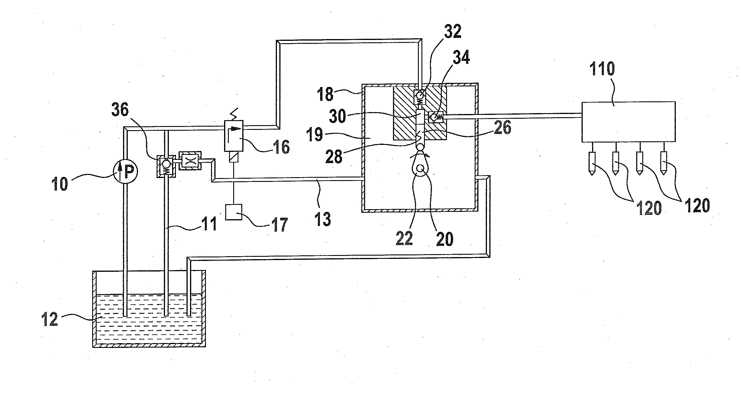
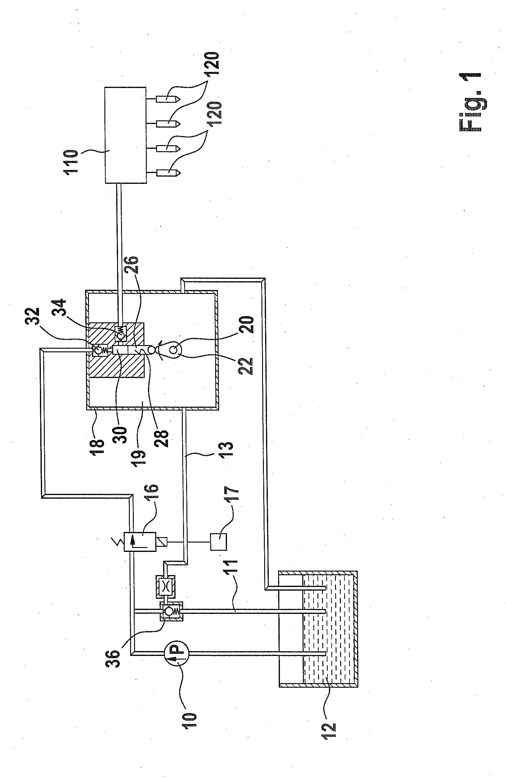
fuel tank. The fuel injection system has a high-pressure pump, by which fuel is delivered by
high pressure to at least one
injector at least indirectly, for instance via a reservoir. By means of a
feed pump, fuel is delivered to the high-pressure pump. The high-pressure pump has at least one pump
piston that is driven in a
reciprocating motion by a drive mechanism disposed in a drive region. The low-pressure region of the fuel injection system extends between the
feed pump and the high-pressure pump, and in this low-pressure region, a low pressure generated by the
feed pump prevails. The low-pressure region communicates with the drive region of the high-pressure pump. Because of the reciprocating motion of the at least one pump
piston, the volume of the drive region varies, since in the outlet-oriented stroke of the pump
piston, the volume of the drive region is increased, and in the inlet-oriented stroke of the pump piston, the volume of the drive region is decreased. As a result, pressure fluctuations are created in the drive region. Especially in the case of a high-pressure pump with only one pump piston, relatively strong pressure fluctuations are created. As a result, pressure fluctuations are generated in the entire low-pressure region as well, and they can impair the function of the fuel injection system. To compensate for these pressure fluctuations, the valve member of the fuel overflow valve must be capable of executing a long stroke, which accordingly necessitates a long stroke of the valve spring as well. This in turn means that a large amount of space is necessary for the valve spring, and the valve spring is heavily loaded and can therefore break.

