Variable force solenoid

a solenoid and variable force technology, applied in the field of variable force solenoids, can solve the problems that the stroke and profile characteristics of the conventional variable force solenoids are not completely satisfactory, and the use of solenoid is not completely satisfactory. achieve the effect of low profile and long strok

Inactive Publication Date: 2007-07-05
BORGWARNER INC
View PDF4 Cites 14 Cited by
  • Summary
  • Abstract
  • Description
  • Claims
  • Application Information

AI Technical Summary

Benefits of technology

[0011] In accordance with the general teachings of the present invention, new and improved variable force solenoids are provided. More specifically, the solenoids of the present invention preferably provide relatively long stroke and relatively low profile. Additionally, the solenoids of the present invention preferably include armatures with at least one tapered surface and pole pieces with at least one tapered surface. Further, the armatures and the pole pieces of the present invention can preferably be provided with tapers on more than one surface thereof.
[0014] As noted, the solenoid of the present invention preferably includes a long stroke, relative to its length, combined with a high and relatively linear force vs. its stroke. Without being bound to a particular theory of the operation of the present invention, the long stroke combined with a high and relatively linear force vs. its stroke is achieved by the control of the cross-sectional area and the angles of the tapered portions of the armature and / or pole piece to provide an advantageous magnetic force vector that maximizes axial force while simultaneously providing increased axial / radial force ratios for low mechanical friction.
[0015] Additional preferred features of the solenoid of the present invention include, without limitation, that: (1) the support for the stem is at least partially located within the inner diameter of the armature; (2) the solenoid has at least a portion that is overmolded with a plastic material; (3) the solenoid has an integrated bracket for attachment; (4) the integral bracket is part of one of the solenoid components; (5) the solenoid has an integrated bracket for attachment that is not attached to the solenoid; (6) the bracket is supported in the solenoid assembly by overmolded plastic; (7) and / or the solenoid has a least one non-magnetic bushing that will both guide the stem and prevent the armature from magnetically “latching” to another magnetic component.

Problems solved by technology

However, conventional variable force solenoids have not been completely satisfactory with respect to their stroke and profile characteristics.
Two problems generally arise if this type of solenoid is used.

Method used


Image

  • Variable force solenoid
  • Variable force solenoid
  • Variable force solenoid

Examples


Embodiment Construction

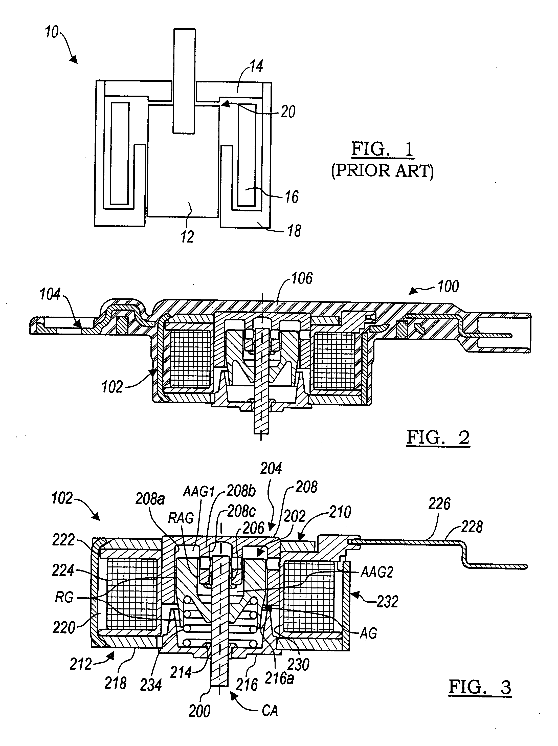
[0043] The following description of the preferred embodiment(s) is merely exemplary in nature and is in no way intended to limit the invention, its application, or uses.

[0044] In accordance with the general teachings of the present invention, a solenoid design is provided that will provide relatively high force over a relatively long stroke. Without being bound to a particular theory of the operation of the present invention, the present invention will achieve this force and stroke with a solenoid length that is relatively small compared to its stroke. Additional features of the present invention include, without limitation, a design for supporting the stem of the solenoid over the entire stroke and the minimization of the radial forces and the resulting bearing friction.

[0045] Referring generally to the Figures, and more specifically to FIG. 2, the solenoid 100, in accordance with the general teachings of the present invention, preferably consists primarily of a solenoid subassem...


PUM

PropertyMeasurementUnit
taper anglesaaaaaaaaaa
heightaaaaaaaaaa

Abstract

A variable force solenoid is described, wherein the solenoid has a relatively long stroke and a relatively low profile. The solenoid includes an armature with at least one tapered surface and a pole piece with at least one tapered surface. The armature and the pole piece may each be provided with multiple tapers on more than one surface thereof.

Description

CROSS-REFERENCE TO RELATED APPLICATIONS [0001] This application is a continuation of U.S. patent application Ser. No. 10 / 863,586 filed on Jun. 8, 2004. This application claims the benefit of U.S. Provisional Application No. 60 / 477,309, filed Jun. 9, 2003. The disclosures of the above applications are incorporated herein by reference.FIELD OF THE INVENTION [0002] The present invention relates generally to variable force solenoids and more particularly to variable force solenoids that include relatively long stroke and relatively low profile characteristics. BACKGROUND OF THE INVENTION [0003] Electric solenoids have been used to provide a number of functions in automotive applications including, but not limited to idle speed control, exhaust gas recirculation valves, fuel vapor purge valves, and the like. Pneumatic actuators were used prior to electrically controlled solenoids. These solenoids were typically characterized as having either a relatively high force over a relatively shor...

Claims


Application Information

Patent Timeline
Patent Type & Authority Applications(United States)
IPC IPC(8): H01F7/08H01F7/13H01F7/16
CPCH01F7/081H01F7/1607H01F7/13
Inventor TELEP, ROBERT J.
Owner BORGWARNER INC
Why Eureka
Try Eureka