
Structure for a suction device

a suction device and structure technology, applied in the field of suction devices, can solve the problems of restricted placement, unglued, unmovable, etc., and achieve the effect of enhancing the suction durability

Active Publication Date: 2010-09-14
FAN EAGLE
View PDF10 Cites 18 Cited by
  • Summary
  • Abstract
  • Description
  • Claims
  • Application Information

AI Technical Summary

Benefits of technology

"The present invention provides a suction device with improved durability and suction effect. It includes a suction unit, a fixing unit, a press unit, and a linkage positioning unit. The press unit is placed between the fixing unit and the suction unit and is pressed against the surface to prevent air leakage. This ensures a tight and durable suction and attachment to the contact surface. The technical effects of the invention are improved suction durability and effect."

Problems solved by technology

The press unit is a rigid object, and the placement is restricted, however, not glued and unmovable, to be located between the fixing unit and the suction unit.

Method used


Image

  • Structure for a suction device
  • Structure for a suction device
  • Structure for a suction device

Examples


Embodiment Construction

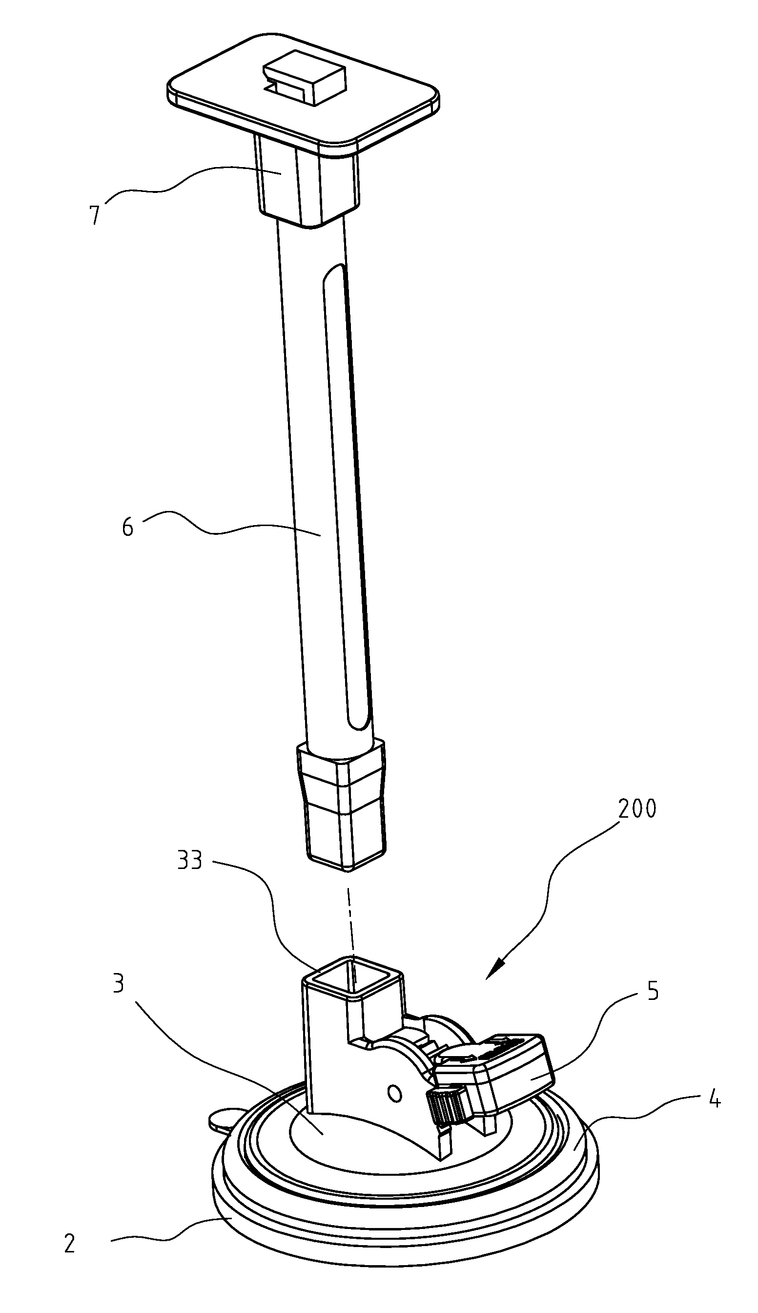
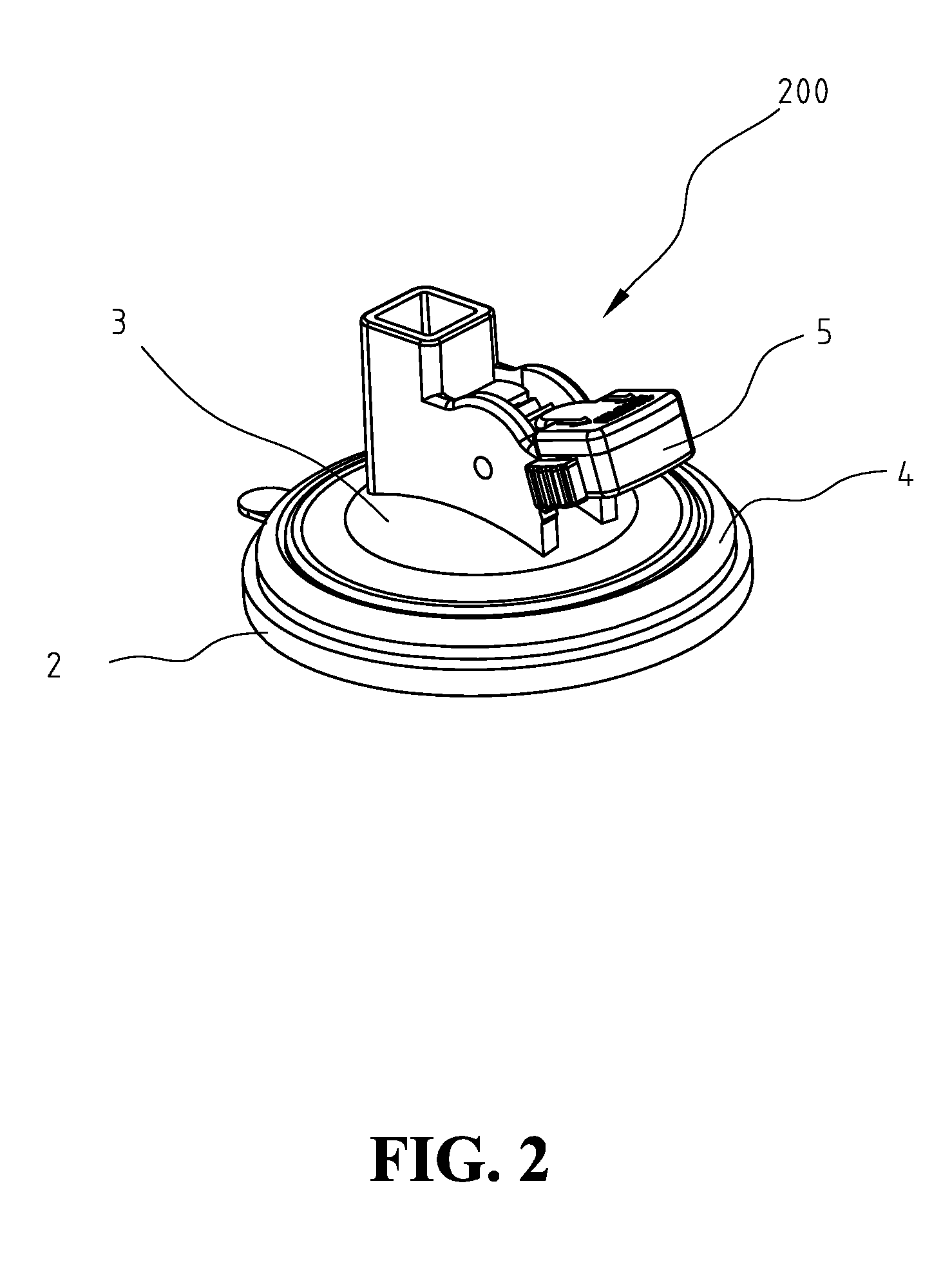
[0017]FIGS. 2 & 3 show a three-dimensional view and a dissected view of the present invention. Suction device 200 of the present invention includes a suction unit 2, a fixing unit 3, a press unit 4 and a linkage positioning 5. Suction unit 2 includes a suction disc 21 and a pulling element 22. The bottom of suction disc 21 is made of a soft material and has a shape of flat surface. Pulling element 22 is pillar-shaped, with the bottom engaged to the central area of the top of suction disc 21. Fixing unit 3 is a shell convex at the central area, located on top of suction disc 21 of suction unit 2. The central area of fixing unit 3 further includes a channel hole 31. Pulling element 22 of suction unit 2 extends through channel hole 31 to above fixing unit 3. Press unit 4 is of a ring shape made of rigid, non-deformable material. Press unit 4 is restricted between the area close to circumference of the bottom of fixing unit 3 and the top surface of suction disc 21 of suction unit 2. Lin...


PUM


Abstract

A suction device is provided, including a suction unit, a fixing unit, a press unit and a linkage positioning unit. The fixing unit is located on top of the suction unit. The press unit is restricted between the area close to circumference of the fixing unit and the top surface of the suction unit. The linkage positioning unit is fixed to above the fixing unit and performs linked movement with the pulling element of the suction unit. When the fixing unit tilts partially by the exerted force of a hanging object, the press unit can still press tightly against the area close to the circumference of the suction unit to maintain a strong suction hold and improve the suction durability.

Description

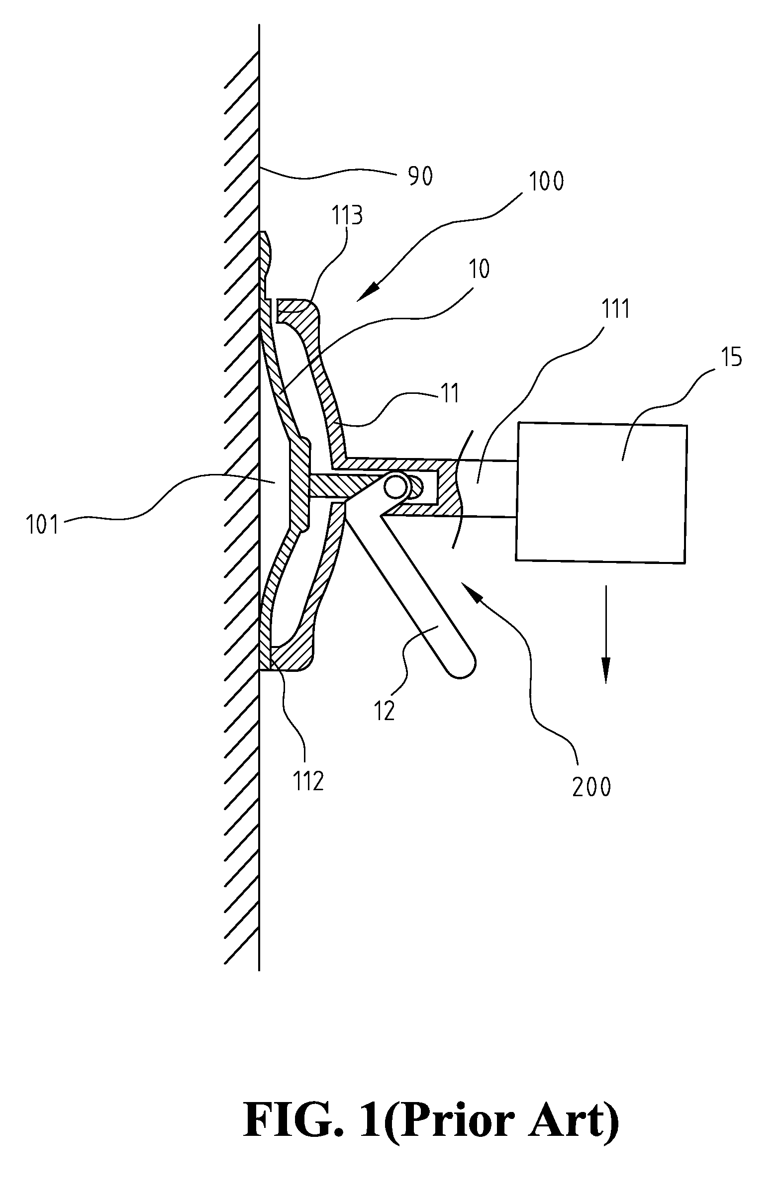
FIELD OF THE INVENTION[0001]The present invention generally relates to a suction device, and more specifically to a structure for a suction device with durable suction.BACKGROUND OF THE INVENTION[0002]FIG. 1 shows a schematic view of a conventional suction device in use. As shown in FIG. 1, suction device 100 includes a suction disc 10, a shell 11 and a wrench unit 12. Shell 11 further includes a connecting element 111 for connecting a heavy object 15 of any kind. In this manner, heavy object 15 can be hung on a vertical surface 90 with a suction device 100. Suction device 100 uses suction disc 10 to attach to vertical surface 90. A compressible space 101 is formed between suction disc 10 and vertical surface 90. Wrench element 12 is for pulling the center of suction disc 10 away from vertical surface 90 so that compressible space 101 is enlarged to create a suction similar to the vacuum suction. In addition, when wrench element 12 moves, wrench element 12 also applies force to shel...

Claims


Application Information

Patent Timeline
Patent Type & Authority Patents(United States)
IPC IPC(8): F16B47/00
CPCF16B47/006F16B47/00B65G49/061B65G2249/045B25B11/00
Inventor FAN, EAGLE
Owner FAN EAGLE
Learn More