
Side airbag apparatus

a side airbag and airbag technology, applied in the direction of pedestrian/occupant safety arrangement, vehicle components, vehicular safety arrangements, etc., can solve the problems of not disclosing the deployment mode of the airbag, the thorax pc might not be sufficiently protected, so as to achieve the effect of protecting the occupants

Inactive Publication Date: 2010-09-14
TOYODA GOSEI CO LTD
View PDF55 Cites 83 Cited by
  • Summary
  • Abstract
  • Description
  • Claims
  • Application Information

AI Technical Summary

Benefits of technology

The present invention provides a side airbag apparatus that can effectively protect occupants in a vehicle. The apparatus includes an airbag, inflator, and gas guiding mechanism or promoting mechanism or delaying mechanism. The airbag is deployed between the body side portion of the vehicle and the seat, and it has an upper chamber, lower chamber, and intermediate chamber that are simultaneously inflated. The gas guiding mechanism guides gas from the inflator to the upper and lower chambers, while the promoting mechanism promotes inflation of the upper and lower chambers compared to the intermediate chamber. The delaying mechanism delays inflation of the intermediate chamber compared to the upper and lower chambers. Overall, the invention provides a more effective and efficient side airbag system for protecting occupants in a vehicle.

Problems solved by technology

However, since the internal pressure of the first chamber 545 corresponding to the thorax Pc is relatively low, if the body side portion of the vehicle is greatly deformed inward of the passenger compartment due to a side collision, the thorax Pc might not be sufficiently protected.
Therefore, like the first prior art, the thorax Pc might not be sufficiently protected.
The third prior art discloses the largely deployable airbag that simply protects the body of an occupant over a large area, but does not disclose any deployment modes of the airbag to correspond to specific parts of the occupant's body.
Therefore, the third prior art is not expected to effectively protect occupants by taking the characteristics of a human body into consideration.

Method used


Image

  • Side airbag apparatus
  • Side airbag apparatus
  • Side airbag apparatus

Examples


first embodiment

[0054]the present invention will now be described with reference to FIGS. 1 to 4.

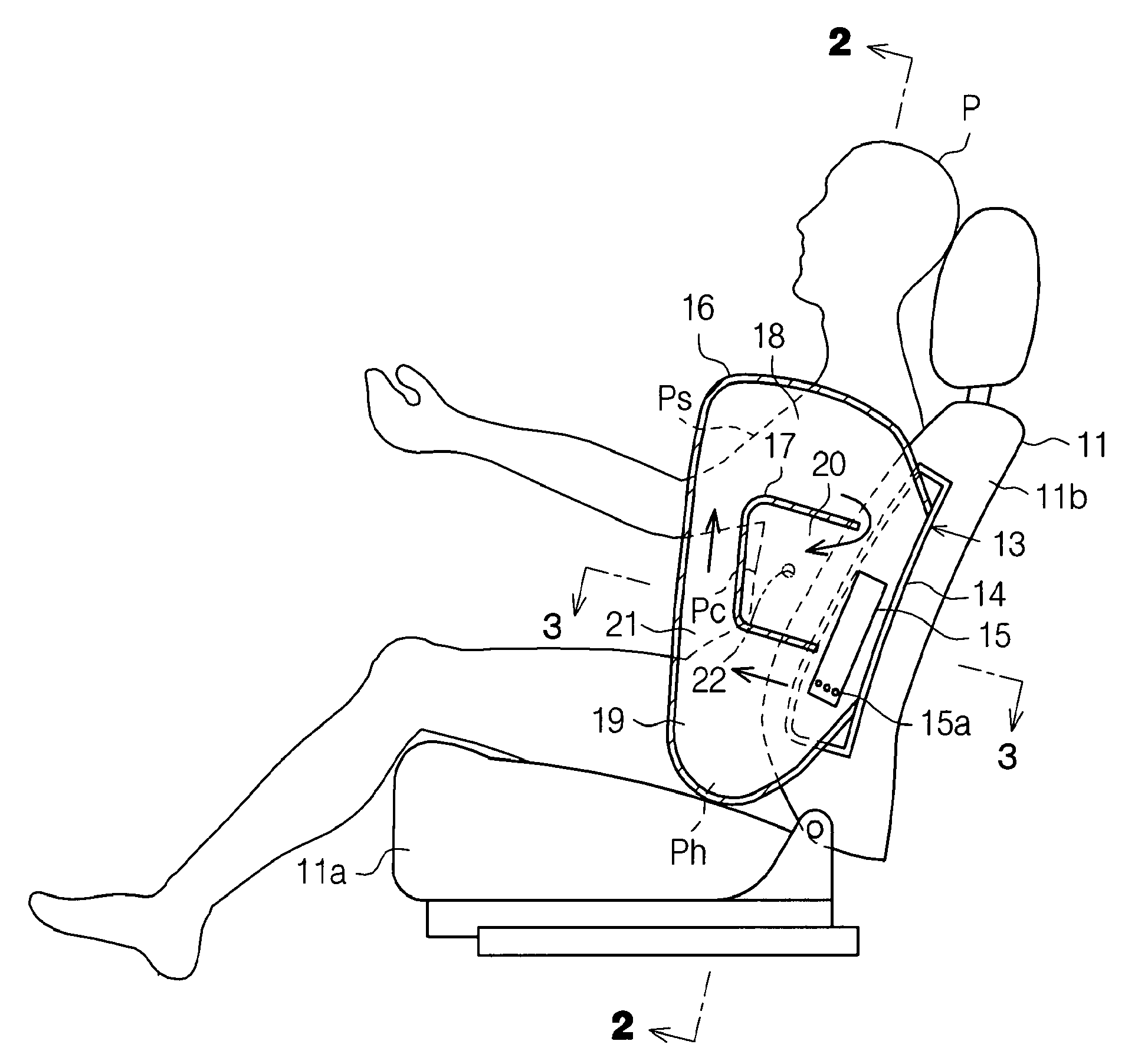
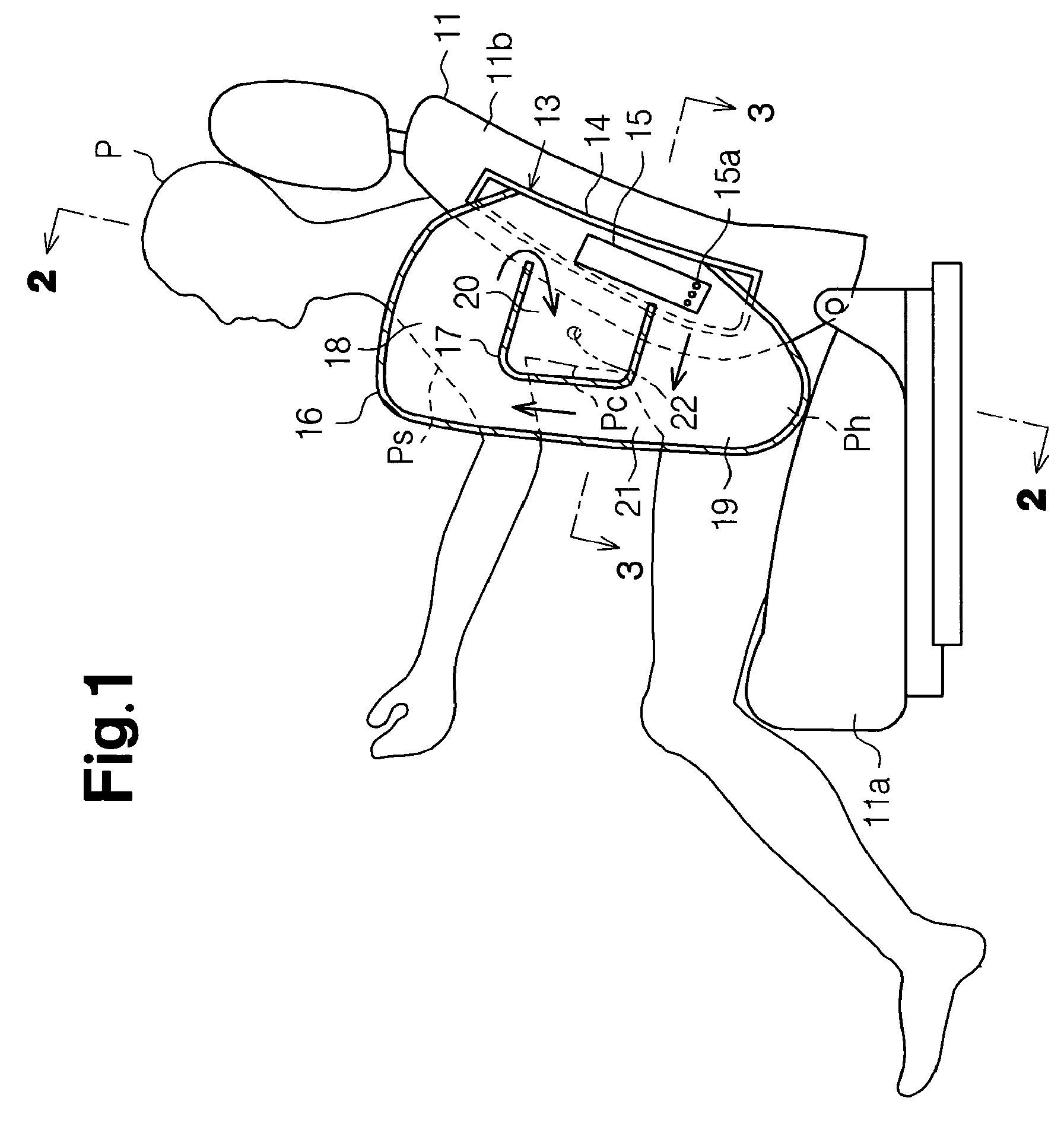
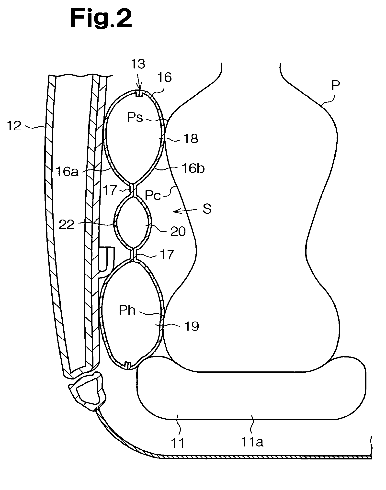
[0055]FIGS. 1 to 3 show a side airbag apparatus 13 provided in a left front seat 11 in a vehicle passenger compartment. The front seat 11 includes a seat portion 11a and a backrest 11b. A case 14 accommodating the side airbag apparatus 13 is embedded in the left portion of the backrest 11b to correspond to a door 12, which consists part of a side portion of the vehicle body. Although only the left front seat 11 is illustrated in the drawings, a right front seat has a similar airbag apparatus in its right portion.

[0056]The side airbag apparatus 13 includes a gas generator, which is an inflator 15, and an airbag 16. The inflator 15 is fixed in the case 14. The airbag 16 covers the inflator 15. The inflator 15 has a case and gas generation agent (not shown) in the case. The gas generation agent generates gas to deploy the airbag 16. Gas portion is formed at a lower portion of the inflator 15. In this embod...

second embodiment

[0076]In the second embodiment, a wide seam 17A is formed in a section of the airbag 16 that is substantially center in the vertical direction. The wide seam 17A is formed by sewing the fabric sheets 16a, 16b. The wide seam 17A extends substantially horizontally to define an upper chamber 18 and a lower chamber 19 in the airbag 16. The wide seam 17A has a gas guiding function and guides gas to substantially simultaneously inflate the upper and lower chambers 18, 19. The wide seam 17A also functions to limit bulging of the intermediate portion of the airbag 16. As shown by arrows in FIG. 5, gas injected from the gas ports 15a of the inflator 15 is first guided to the lower chamber 19. The gas is then guided to the upper chamber 18 from the lower chamber 19 along the wide seam 17A via the gas passage 21. The gas is substantially simultaneously guided into the upper and lower chambers 18, 19.

[0077]When the airbag 16 is deployed, the upper chamber 18 and the lower chamber 19 are inflate...

third embodiment

[0081]In the third embodiment, as shown in FIG. 7, the airbag 16 has two seams 17, which are formed by sewing the fabric sheets 16a, 16b to each other. The seams 17 are spaced vertically by a predetermined distance. The seams 17 define an upper chamber 18, a lower chamber 19, and an intermediate chamber 20 in the airbag 16. When forming each seam 17, the fabric sheets 16a, 16b are sewed such that the intermediate sections of the fabric sheets 16a, 16b will be restrained when the airbag 16 is deployed. Thus, when the airbag 16 is deployed, the intermediate chamber 20 is thinner than the upper and lower chambers 18, 19. That is, the seams 17 function to limit bulging of the intermediate chamber 20. The thicknesses of the chambers 18 to 20 are represented by the measurements along a direction perpendicular to the surface of the sheet of FIG. 7. A cover 24 is located about the inflator 15. The cover 24 defines an introducing chamber 25 into which gas injected from the gas ports 15a of t...


PUM


Abstract

A side airbag apparatus for vehicle has an airbag and an inflator. An upper chamber, a lower chamber, and an intermediate chamber are defined by a seam in the airbag. When the airbag is deployed, the upper chamber corresponds to a shoulder of an occupant, the lower chamber corresponds to a lumbar region of the occupant, and the intermediate chamber corresponds to a thorax of the occupant. The seam guides gas from the inflator to the upper and lower chambers such that the upper and lower chambers are substantially simultaneously inflated, and the intermediate chamber is inflated after a delay. The thickness of the intermediate chamber is less than the thicknesses of the upper and lower chambers. As a result, the occupant of the vehicle is effectively protected.

Description

CROSS REFERENCE TO RELATED APPLICATION[0001]This application is a continuation application of U.S. Ser. No. 10 / 382,642, which was filed on Mar. 7, 2003, and such parent application (U.S. Ser. No. 10 / 382,642) is hereby incorporated by reference.BACKGROUND OF THE INVENTION[0002]The present invention relates to an airbag apparatus having an airbag that is deployed at a side of an occupant of a vehicle when an impact of a force greater than a predetermined value is applied to a side of the vehicle body due to a side collision.[0003]Such side airbag apparatuses have been disclosed in, for example, Japanese Laid-Open Patent Publication No. 2000-177527 (first prior art), Japanese Laid-Open Patent Publication No. 2000-280853 (second prior art), and U.S. Pat. No. 5,112,079 (third prior art).[0004]In the first prior art, as represented by FIG. 34, a side airbag apparatus 542 is mounted in a backrest 541a of a vehicle seat 541 as shown in FIG. 34. The interior of an airbag 543 of the side airb...

Claims


Application Information

Patent Timeline
Patent Type & Authority Patents(United States)
IPC IPC(8): B60R21/16B60R21/231B60R21/235
CPCB60R21/23138B60R21/235
Inventor SATO, EIJITANASE, TOSHINORIMABUCHI, SATOSHIKOYAMA, TORUNARUSE, MOTOAKI
Owner TOYODA GOSEI CO LTD
Learn More