
Camera support for cinematography equipment

a technology for cinematography equipment and camera supports, applied in the field of camera supports, can solve the problems of unsteady camera support, lack of smooth camera movement, and noise generated by movemen

Inactive Publication Date: 2010-09-14
SAAD PHILIP +1
View PDF15 Cites 10 Cited by
  • Summary
  • Abstract
  • Description
  • Claims
  • Application Information

AI Technical Summary

Benefits of technology

[0008]It is an additional object of the invention herein to provide a camera support that is steady, smooth and quiet in its operation.

Problems solved by technology

Such drawbacks include unsteady support of the camera, lack of smooth movement of the camera, and noise generated by the movement.
In particular, it is difficult for a camera operator to achieve smooth and steady movement of the camera on the camera support while filming.
Also, limitations exist in positioning the camera, i.e. either the amount of movement is limited and the option of top-mounting or under-mounting the camera on a camera support has not existed.
The existing camera supports are also noisy, to the point that they create an unwanted intrusion into simultaneous sound recordings.

Method used


Image

  • Camera support for cinematography equipment
  • Camera support for cinematography equipment
  • Camera support for cinematography equipment

Examples


Embodiment Construction

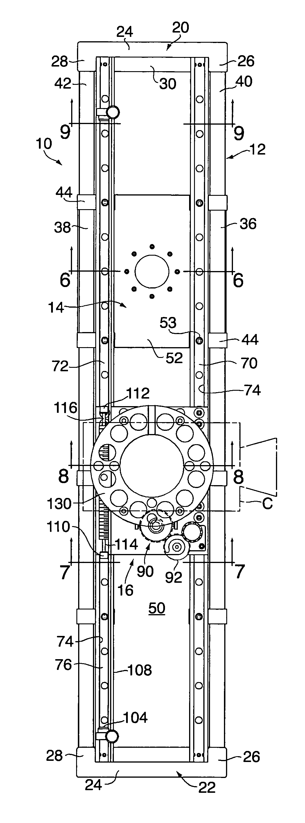
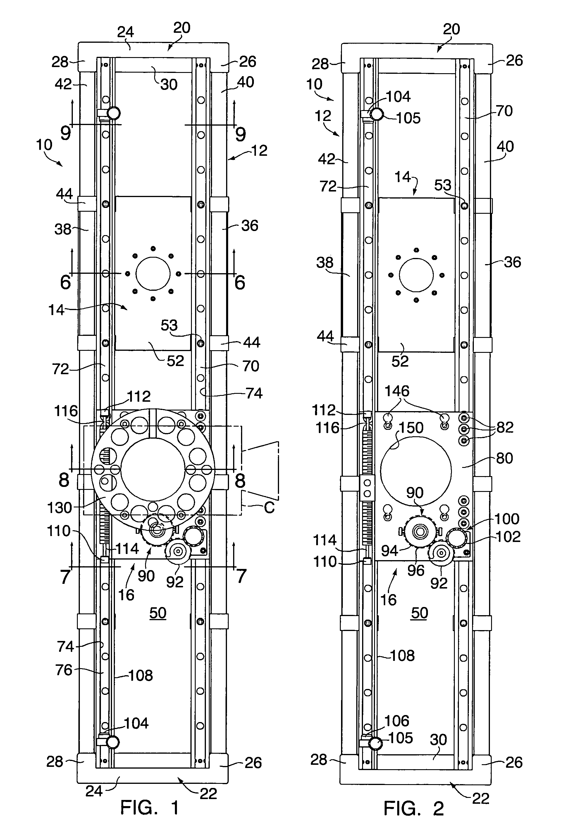
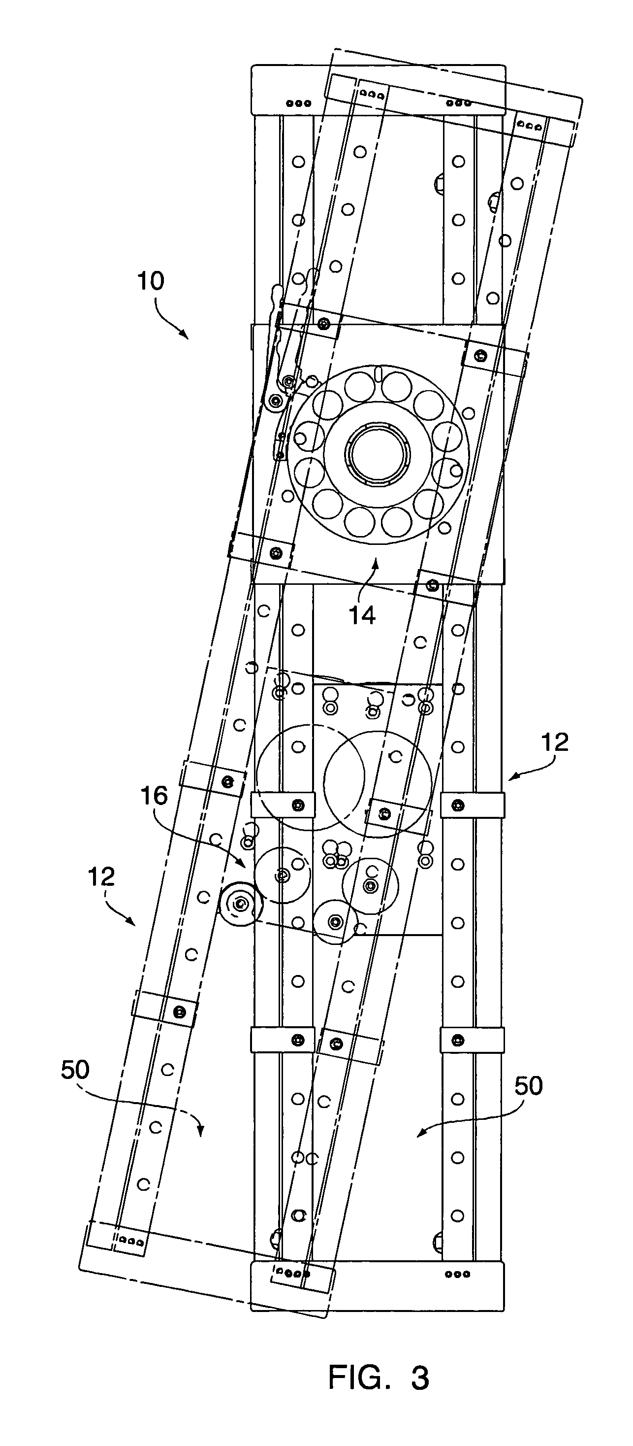
[0028]A camera support 10 is shown in the various figures and generally comprises a perimeter frame 12, a mounting assembly 14 for mounting the camera support on a secondary support, such as a camera dolly, boom or tripod T, and a trolley assembly 16 for mounting a camera C or other piece of cinematography equipment to the camera support 10. The mounting assembly 14 provides for panning by rotating the camera support on the secondary support, and the trolley assembly 16 provides for translating the camera C along the length of the perimeter frame 12.

[0029]As seen in FIGS. 1 and 2, the perimeter frame 12 has two end blocks 20 and 22. Both end blocks 20 and 22 are generally U-shaped with the base 24 of the U providing the ends of the perimeter frame 12 and the legs 26, 28 of the U extending from the base 24. Additionally, a cross flange 30 extends between the legs 26 and 28. The end blocks 22, 24 may be provided with handle holes 32 seen on FIGS. 6 and 9 for lifting the camera support...


PUM


Abstract

The camera support for cinematography equipment has end blocks and side beams forming a perimeter frame with an open central area. The perimeter frame is adapted to mount to a secondary support. Track rails extending along the side beams slidingly mount a trolley plate on rollers received in track slots and a camera is mounted to the trolley plate for sliding movement along the perimeter frame. The camera may be mounted above the trolley plate or below the trolley plate where it is accommodated by the open central area. The trolley plate is mounted on rollers received in slots designed by the track rails, and a magnetic friction device provides controlled resistance to translation.

Description

RELATED APPLICATION[0001]This application claims priority to our U.S. Provisional Application Ser. No. 60 / 850,592 filed Oct. 10, 2006.FIELD OF INVENTION[0002]The invention herein relates to a camera support adapted for mounting to a secondary support such as a camera dolly, boom or tripod, wherein the camera support mounts and permits movement of cinematography equipment, and particularly cameras.BACKGROUND OF INVENTION[0003]The creative aspects of cinematography require that cameras, or other such cinematography equipment including film cameras, video cameras, digital cameras as well as potentially other equipment, be moveable to achieve a desired image or effect. As used herein, the term “camera” will be used to refer to all such cinematography equipment, both existing and yet to be developed or used in the same or similar manner as existing equipment. The images or effects that may be desired may be achieved by changing the angle or distance at which relatively stationary subject...

Claims


Application Information

Patent Timeline
IPC IPC(8): G03B17/00
CPCG03B17/00
Inventor SAAD, PHILIPDALTON, JEREMIAH
Owner SAAD PHILIP
Learn More