
Liquid crystal display apparatus and method of driving

a technology of liquid crystal display and apparatus, applied in the direction of static indicating devices, non-linear optics, instruments, etc., can solve the problems of reducing reducing and reducing the light transmittance and the degree of color purity of filters, so as to achieve the effect of maximizing the luminance of the lcd apparatus

Inactive Publication Date: 2010-09-14
SAMSUNG DISPLAY CO LTD
View PDF4 Cites 2 Cited by
  • Summary
  • Abstract
  • Description
  • Claims
  • Application Information

AI Technical Summary

Benefits of technology

[0006]The light-transmittance response waveform of the liquid crystal is sequentially delayed by a constant predetermined interval from the first gate line to the last gate line. The light-transmittance response waveform corresponding to the first gate line reaches a peak value in a first maximum light-transmitting time and the light-transmittance response waveform corresponding to the last gate line reaches a peak value in a second maximum light-transmitting time. For example, one frame is divided into four periods and the light-emitting unit generates red, green, blue and white lights in respective corresponding periods. The time interval between a light emitting unit reaching its a maximum output and the ending of its light output lies in the range of about 0.15 ms to about 0.17 ms. The light-emitting interval may be determined so that a sum of integral values calculated by integrating light-transmittance response waveforms respectively corresponding to from the first gate line to the last gate line of the part of the LCD panel multiplied by a light-emitting signal of the light-emitting unit for an integral interval of the light-emitting interval is maximized. According to the present invention, the driving time of the liquid crystal and light-emitting time of the light-emitting unit is optimized to maximize the luminance of the LCD apparatus.

Problems solved by technology

Unfortunately, this reduces resolution by about one third and the filters reduce light transmittance and the degree of color purity.
However, the above driving time is not an optimized driving time, so that improvement of luminance of the LCD apparatus is limited.

Method used


Image

  • Liquid crystal display apparatus and method of driving
  • Liquid crystal display apparatus and method of driving
  • Liquid crystal display apparatus and method of driving

Examples


Embodiment Construction

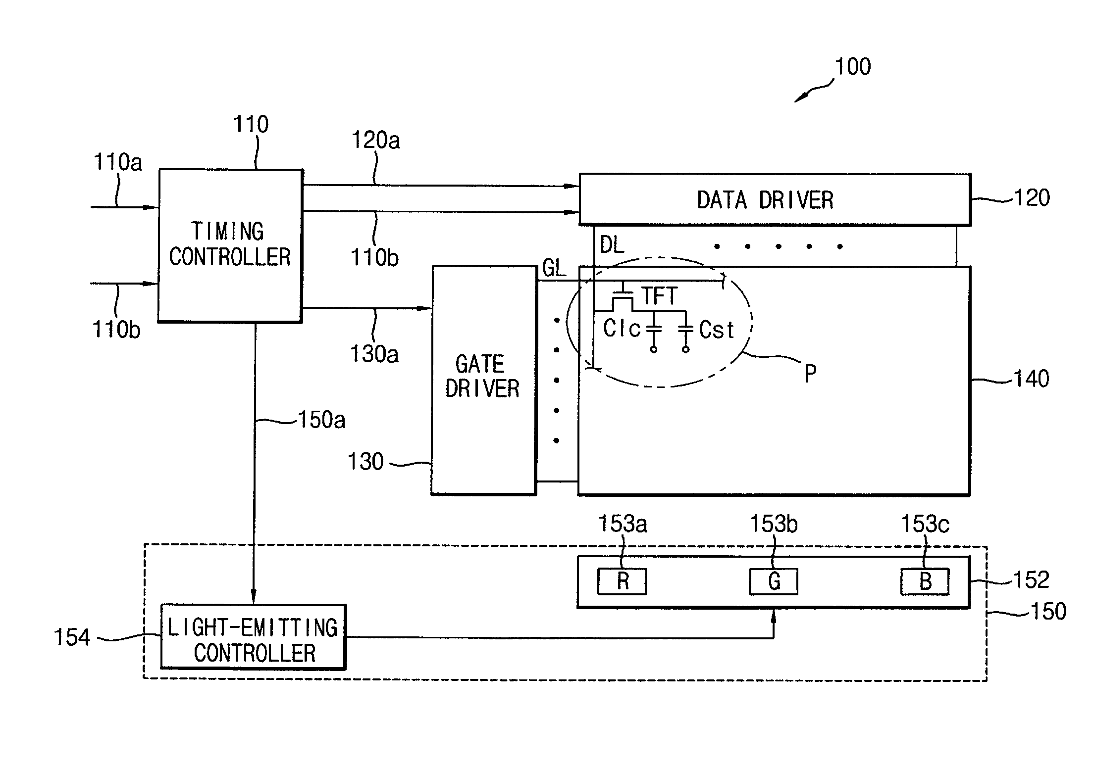
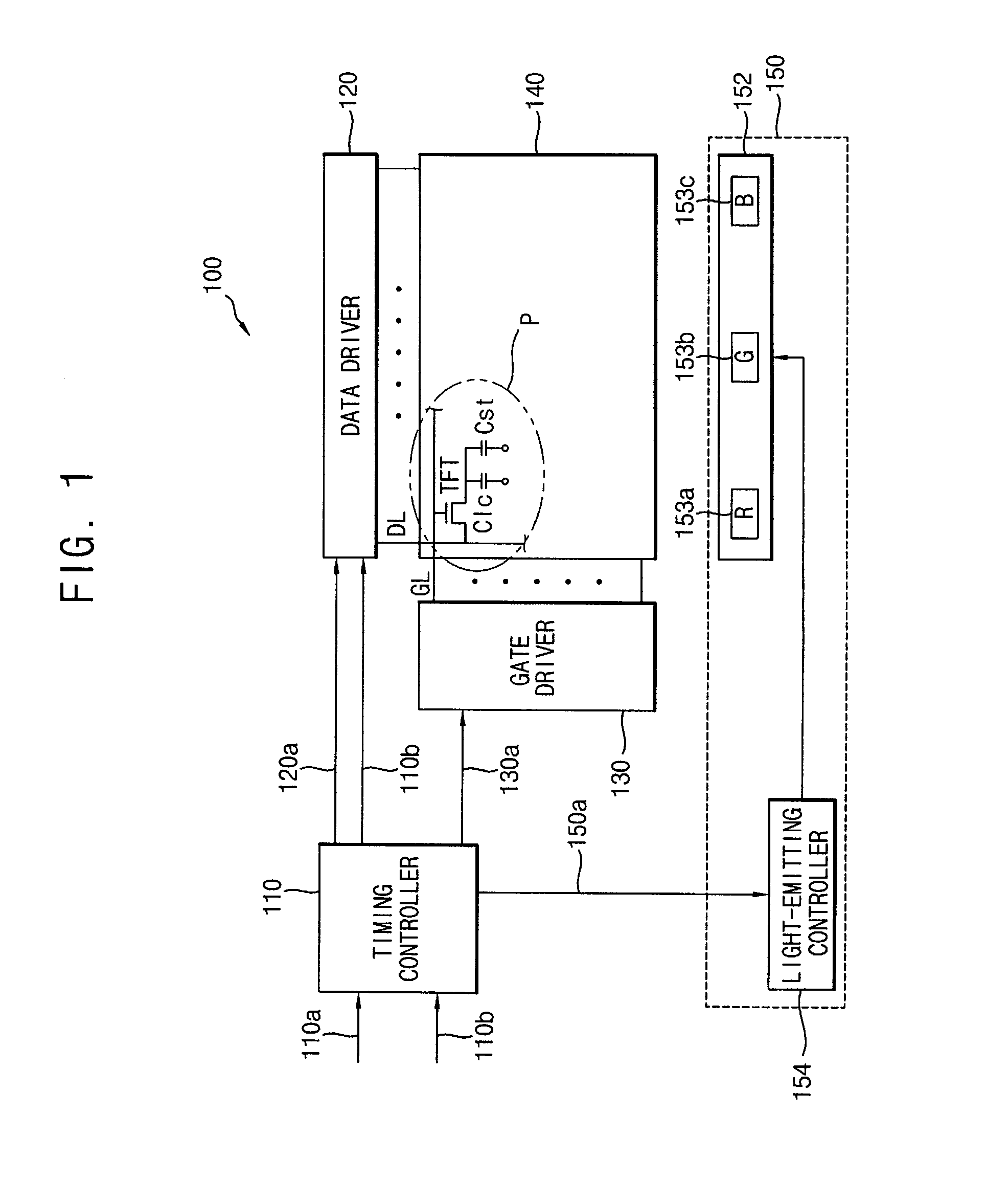
[0013]FIG. 1 is a block diagram illustrating a liquid crystal display (LCD) apparatus in accordance with an exemplary embodiment of the present invention.

[0014]Referring to FIG. 1, LCD apparatus 100 includes a timing controller 110, a data driver 120, a gate driver 130, an LCD panel 140 and a backlight unit 150. LCD apparatus 100 displays a color image of a frame by dividing the frame into a plurality of periods in which different colors are displayed, respectively.

[0015]Timing controller 110 receives a timing control signal 110a and a data signal 110b from an external device such as a graphic controller, etc. e Timing controller 110 generates and outputs various control signals for driving LCD apparatus 100 in response to the timing control signal 110a. For example, timing controller 110 outputs a data control signal 120a controlling data driver 120, a gate control signal 130a controlling gate driver 130 and a backlight control signal 150a controlling backlight unit 150.

[0016]In re...


PUM


Abstract

A liquid crystal display (LCD) apparatus includes an LCD panel and light-emitting units. The light-emitting units generate lights in a corresponding light-emitting interval to illuminate a part of the LCD panel corresponding to the light-emitting units. A light-emitting ending point of the light-emitting interval is disposed between a first maximum light-transmitting time of a first region of the part of the LCD panel and a second maximum light-transmitting time of a second region of the part of the LCD panel, the first region corresponding to the first gate line of gate lines belonging to the part of the LCD panel illuminated by the light-emitting unit and the second region corresponding to the last gate line of the gate lines.

Description

CROSS-REFERENCE TO RELATED APPLICATIONS[0001]This application claims priority to Korean Patent Application No. 2006-36955 filed on Apr. 25, 2006, and all the benefits accruing there from under 35 U.S.C. §119, the contents of which are herein incorporated by reference.FIELD OF THE INVENTION[0002]The present invention relates to a liquid crystal display (LCD) apparatus capable of displaying a color image by dividing a frame into a plurality of periods in which different colors are displayed.DESCRIPTION OF THE RELATED ART[0003]Generally, an LCD apparatus includes a plurality of display pixels, each of which has three-colored color filters and uses a source of white light. Unfortunately, this reduces resolution by about one third and the filters reduce light transmittance and the degree of color purity. An alternative approach uses the CFL time-sequence driving method which divides a frame into three successive periods of red, green and blue lights furnished by respective light-emitting...

Claims


Application Information

Patent Timeline
Patent Type & Authority Patents(United States)
IPC IPC(8): G09G3/36
CPCG02F1/133603G09G3/3413G09G2310/024G02F2001/133622G02F1/133622G02F1/133G09G3/20G09G3/36
Inventor SHIN, SEONG-SIKLEE, JONG-SEOHAN, JUNG-SUKJUN, TAE-JONGLEE, JOO-YOUNG
Owner SAMSUNG DISPLAY CO LTD
Learn More