Frequency domain based MICR reader

a frequency domain and micr reader technology, applied in the field of micr (magnetic ink character recognition), can solve the problems of system vulnerability and interfere with character discrimination capabilities, and achieve the effect of easy filtering ou

Inactive Publication Date: 2010-09-14
LINKEDIN
View PDF13 Cites 4 Cited by
  • Summary
  • Abstract
  • Description
  • Claims
  • Application Information

AI Technical Summary

Problems solved by technology

However, such systems are still vulnerable to noise that can interfere with their character discrimination capabilities.

Method used


Image

  • Frequency domain based MICR reader
  • Frequency domain based MICR reader
  • Frequency domain based MICR reader

Examples


Embodiment Construction

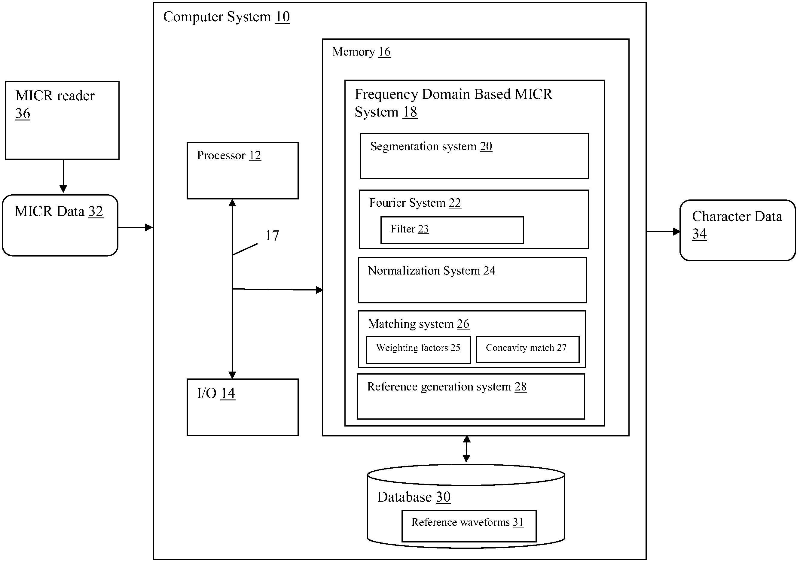
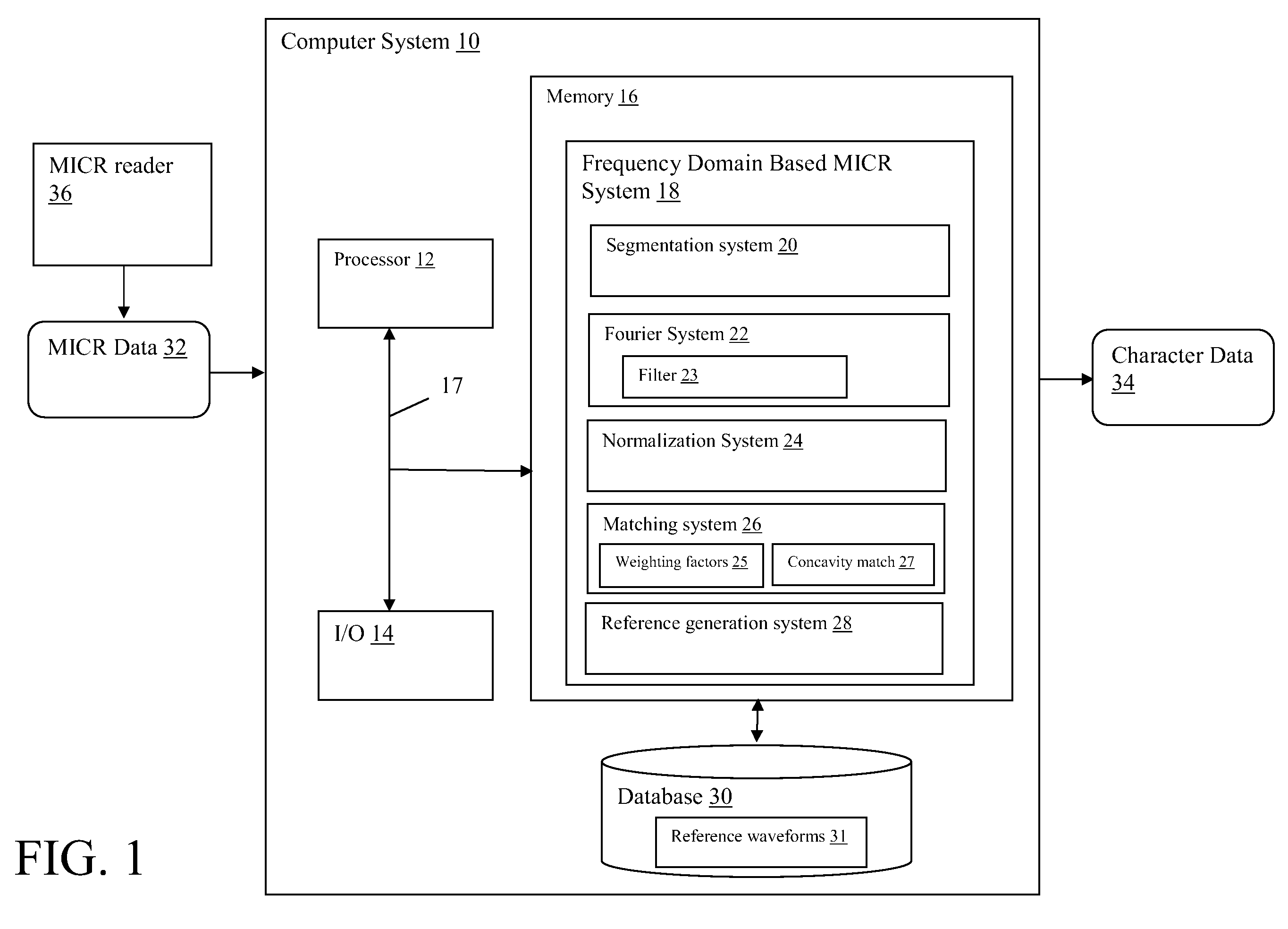
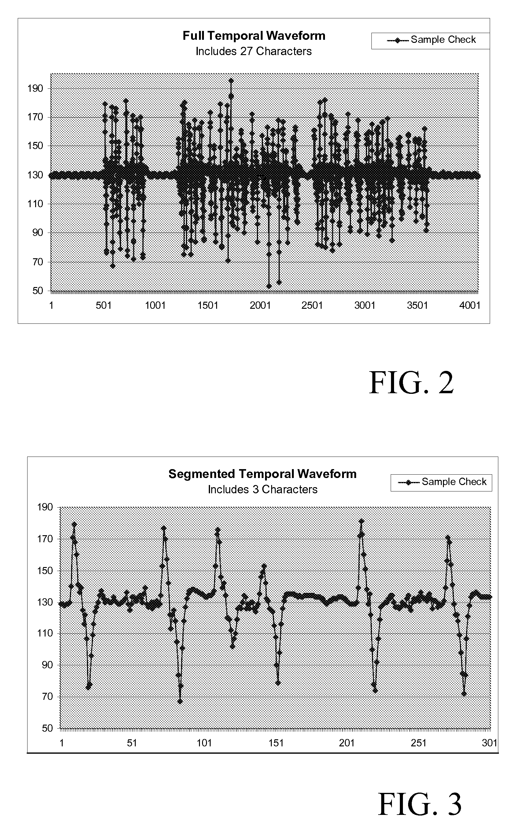
[0020]Referring now to the drawings, FIG. 1 depicts a computer system 10 having a frequency domain based MICR system 18 that processes inputted MICR data 32 and generates recognized character data 34. MICR data 32 general includes temporal waveform signals obtained from a MICR reader 36 that reads characters printed with magnetic ink, such as those found on the code line of a bank check. For instance, in the case of a single gap MICR reader, magnetic data is collected as the “gap” passes over the code line. In one common, but not limiting, application, code lines are printed using 14 possible characters (0-9 and four special characters) in E13B font. FIG. 2 depicts an example of a temporal waveform obtained from a MICR reader 36 from of a sample bank check having 27 characters in the code line. FIG. 3 depicts a segmented waveform view of three of the characters from the waveform of FIG. 2.

[0021]Rather than analyze the waveform data in the temporal domain to perform character recogni...


PUM


Abstract

A system and method for implementing frequency domain based magnetic ink character recognition (MICR). A system is provided that includes: a segmentation system for segmenting inputted MICR data into sets of temporal data for inputted characters; a Fourier system for generating a set of Fourier components from temporal data for an inputted character; a normalization system for normalizing the set of Fourier components to generate a normalized set of Fourier components; and a matching system for comparing the normalized set of Fourier components with each of a set of reference waveforms to determine an identity of the inputted character.

Description

FIELD OF THE INVENTION[0001]The invention relates generally to MICR (magnetic ink character recognition), and more particularly, to a system and method for implementing a frequency domain based MICR reader.BACKGROUND OF THE INVENTION[0002]MICR (magnetic ink character recognition) technology is commonly deployed by banks and other financial institutions for reading code line character data, such as account and routing information typically found on bank checks. Because MICR utilizes magnetic, as opposed to optical, information to read character data, MICR readers are generally immune to optical noise.[0003]Single gap MICR readers, which are vastly popular in check processing applications, utilize technology that transduces characters based on temporal signals from a single gap magnetic read-head. Such readers typically implement refined signal processing to improve the accuracy of the read. However, such systems are still vulnerable to noise that can interfere with their character di...

Claims


Application Information

Patent Timeline
Patent Type & Authority Patents(United States)
IPC IPC(8): G06K9/00
CPCG06K7/084
Inventor PRAKASH, RAVINDER
Owner LINKEDIN
Why Eureka
Try Eureka