
Method of detecting the orientation of an object in an image

Inactive Publication Date: 2010-09-14
AGFA NV
View PDF13 Cites 6 Cited by
  • Summary
  • Abstract
  • Description
  • Claims
  • Application Information

AI Technical Summary

Problems solved by technology

Furthermore, the thorax edge orientation may not be standardized, e.g. it may either touch the left or right or the upper or lower image border.

Method used


Image

  • Method of detecting the orientation of an object in an image
  • Method of detecting the orientation of an object in an image
  • Method of detecting the orientation of an object in an image

Examples


Embodiment Construction

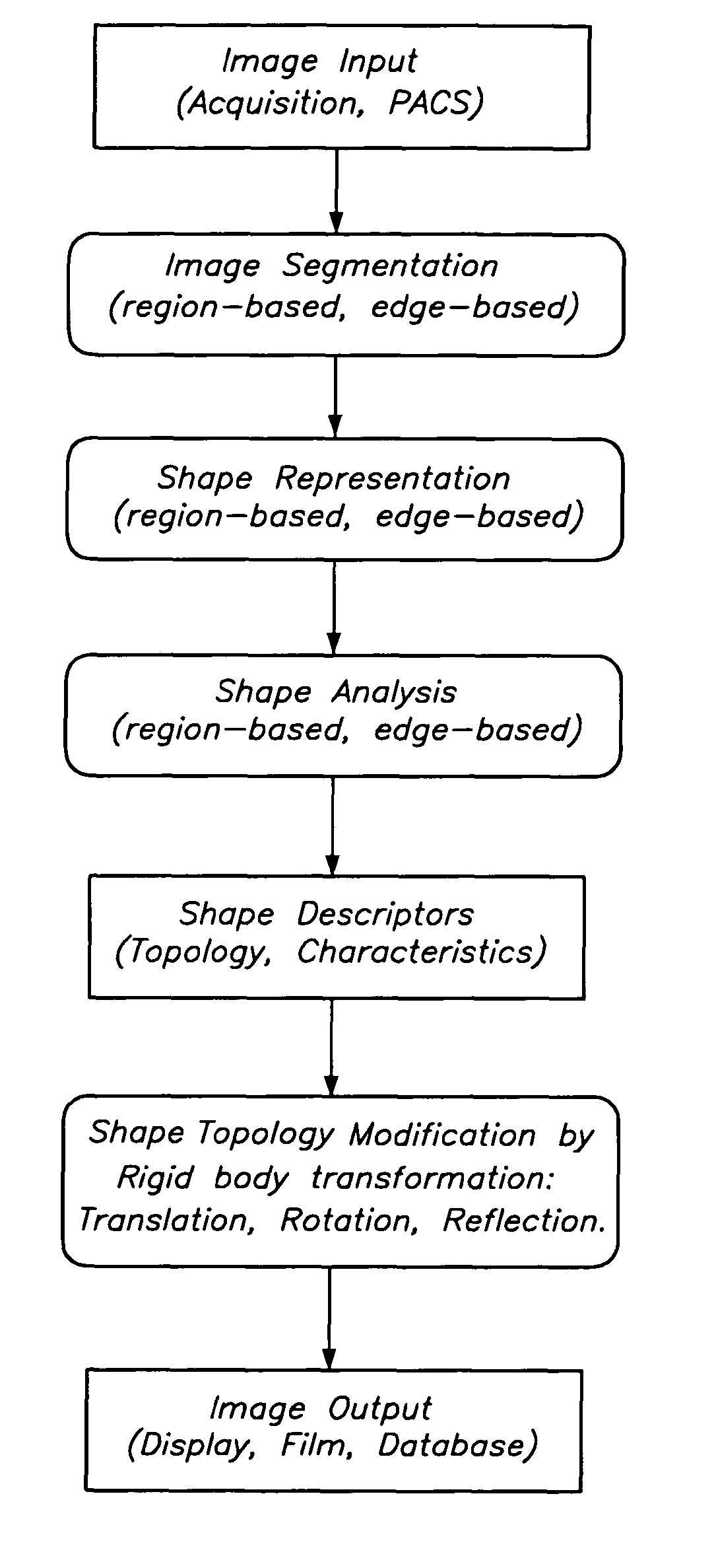
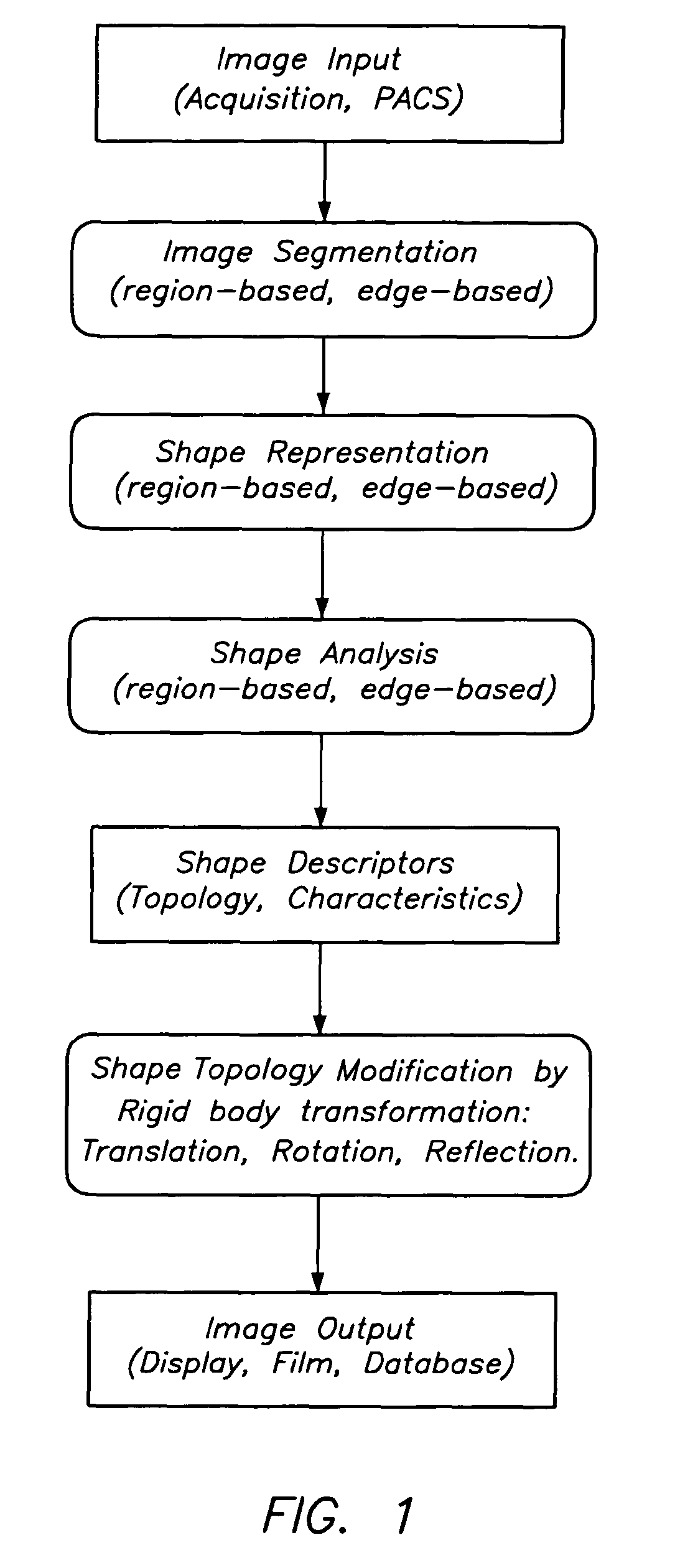
[0025]A general overview of a method to manipulate a radiation image according to the shape of objects in the diagnostic region(s) of the image is given in FIG. 1.

[0026]Image Input:

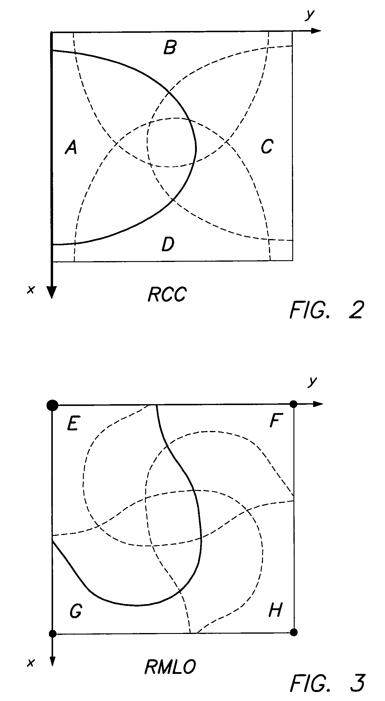
[0027]In order to conduct a topological analysis of the mammography image to infer the position of the breast's thorax side and the orientation of the nipple, shape analysis is performed.

[0028]Shape analysis is generally carried out starting from an intermediate representation of an image typically involving the segmented image and / or special shape descriptors.

[0029]A radiation image typically consist of three different areas:[0030]The diagnostic area comprises pixels corresponding to patient anatomy. In general, the outline of this imaged area may take any shape.[0031]The direct exposure area is the image region that has received un-attenuated radiation. Although this region has constant intensity corrupted by noise only, inhomogenities in incident energy (e.g. X-ray source Heel effect) and receptor (e.g...


PUM


Abstract

A method of detecting the orientation of a radiographic image represented by a digital signal representation wherein mathematical moments of the digital signal representation are calculated relative to different reference entities and wherein a decision on the orientation of the radiographic image, for example the position of the thorax edge in a mammographic image, is obtained on the basis of an extreme value (minimum, maximum) of the calculated moments.

Description

[0001]This application claims the benefit of and the priority to U.S. Provisional Patent Application No. 60 / 450,857 filed Feb. 27, 2003, and to European Patent Application No. 03100375.9 filed Feb. 19, 2003, both of which are incorporated by reference.FIELD OF THE INVENTION[0002]The present invention relates to a method for detecting the orientation of object shapes in radiation images.BACKGROUND OF THE INVENTION[0003]In radiological practice, it is common to display different exposures pertaining to a patient study in a predefined format. This feature is known as a hanging protocol. In film-based operation, it means that the radiologist or operator hangs the films on the light box in a specific spatial arrangement according to standard or local preferences. Determination of the orientation or reflection of an examination type, or verification of it when it is available, is beneficial to the correct display of many examination types.[0004]In screening mammography standard 4-views of...

Claims


Application Information

Patent Timeline
IPC IPC(8): G06K9/32G06K9/36G06K9/00G06T7/00G06T7/60
CPCG06K9/3208G06K9/525G06T7/0042G06T7/606G06T7/73G06T7/66G06V10/242G06V10/435
Inventor DEWAELE, PIET
Owner AGFA NV
Learn More