Hinge structure for an electronic device

a technology of electronic devices and hinges, applied in the field of hinge structures, can solve the problems of increasing costs, requiring a lot of space for hinge structures extending over the whole back of the device, and relatively complex conventional hinge structures for mobile phones

Inactive Publication Date: 2010-09-21
HTC CORP
View PDF14 Cites 10 Cited by
  • Summary
  • Abstract
  • Description
  • Claims
  • Application Information

AI Technical Summary

Benefits of technology

[0009]To attain this purpose, the hinge structure according to the invention is primarily characterized in that it makes it possible to rotate the first body part and the second body part of the device in relation to the axis of rotation of the hinge structure, the hinge structure comprising at least a hinge element which comprises a first hinge half and a second hinge half which are arranged to be movable in relation to each other by means of a pivot placed on the axis of rotation, and which hinge element is arranged to be connected by the first hinge half to the first body part of the device and by the second hinge half to the second body part, wherein the hinge structure comprises a shield structure for shielding the back of the device, the shield structure being connected to the hinge element, and the shield structure being arranged to be movable in a direction perpendicular to the axis of rotation.
[0010]The method according to the invention, in turn, is primarily characterized in that it makes it possible to rotate the first body part and the second body part of the device in relation to the axis of rotation of the hinge structure, in which method the first body part is connected to the second body part by a hinge element in such a way that the hinge element is connected by the first hinge half to the first body part of the device and by the second hinge half to the second body part, the hinge halves being arranged to be movable in relation to each other by means of a pivot placed on the axis of rotation, wherein the hinge element is connected to a shield structure for shielding the back of the device, and the shield structure moves in the direction perpendicular to the axis of rotation during the movement of the body parts.
[0017]The shield structure in the hinge structure protects possible joint structures, such as wires and / or flexible printed circuit boards. Furthermore, the shield structure prevents fingers and pieces of clothing from being trapped between the device.
[0018]In some embodiments of the invention, functional units connected to the hinge structure, such as various cameras and exchangeable modules, are possible. The device can thus be made as versatile as possible without making its size too large. The exchangeable modules, in turn, make it possible to assemble the device to meet the needs of the user.
[0019]The invention has several advantages to structures of prior art. In one embodiment, the simplicity of the hinge structure reduces the number of components, reduces the costs and facilitates the assembly of the device. The structure is durable, because it has no parts that wear, as such. Moreover, the structure as such does not comprise any moving or loose parts, which also increases the serviceable life. In another embodiment, in turn, clearly more space is left inside the housing, for example, for auxiliary devices.
[0020]The solution according to the invention can be used in various devices, such as, for example, portable and hand-held devices. For example, the device can be a mobile phone, a personal digital assistant, a communication device, a camera, and / or a game device. Generally, the invention is well suited for applications in which, at times, the device should be small in size, for example when carried, and at other times, in turn, it should have a relatively large area, for example for controlling functions and / or displaying information. In some embodiments, the foldable structure also forms a shield structure for the means of the device when the device is not opened into the operating position. Thus, for example, the keypad, the display and / or the camera objective can be protected during transportation.

Problems solved by technology

The conventional hinge structures for mobile phones are relatively complex, wherein the assembly of the device requires work stages which increase the costs.
Furthermore, the hinge structures extending over the whole back of the device require a lot of space compared to the other structures, wherein the size of the whole device becomes larger due to the hinge structure.

Method used


Image

  • Hinge structure for an electronic device
  • Hinge structure for an electronic device
  • Hinge structure for an electronic device

Examples


Embodiment Construction

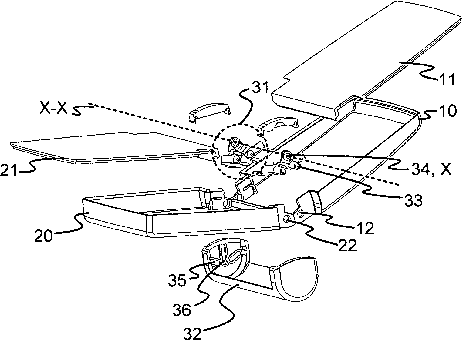
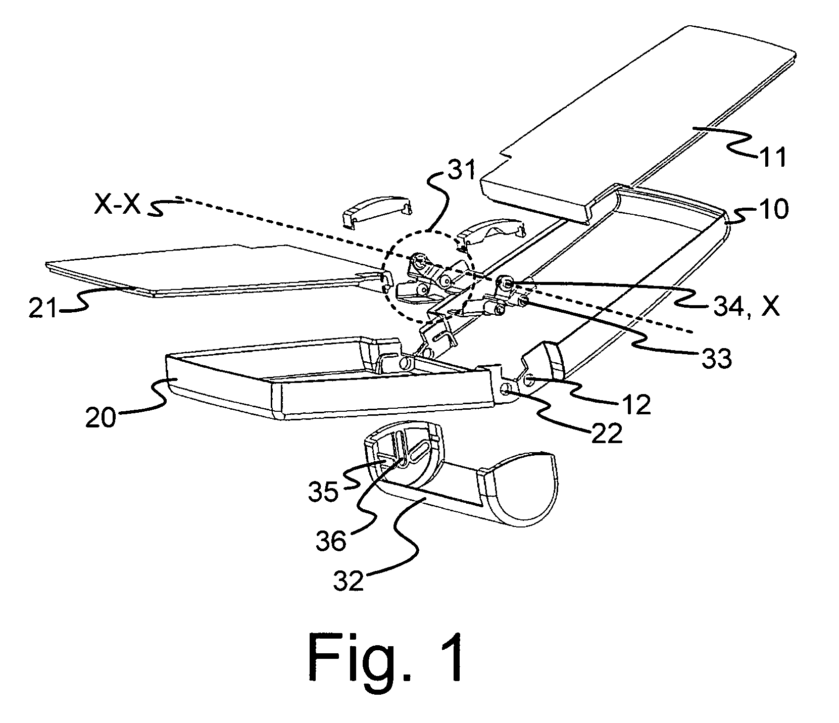
[0037]FIG. 1 is a so-called exploded view showing one embodiment of the invention. In the figure, the first body part 10 of the device is connected to the second body part 20 of the device with a hinge structure that makes it possible to fold the inner surfaces 11, 21 of the body parts substantially against each other. The inner surfaces 11, 21 may comprise various structures of the device, such as, for example, a keypad, a display, a speaker, a microphone, a control structure, etc.

[0038]In the mobile station according to the example, the hinge structure comprises two hinge elements 31 which are placed at each end of the hinged edge of the device, connecting the first body part 10 and the second body part 20. In the device, the pivots X of the hinge element 31 are placed substantially on the same line of axis X-X. This line of axis X-X constitutes the axis of rotation of the device, with respect to which the body parts 10, 20 of the device can be folded. Furthermore, the hinge struc...


PUM


Abstract

A hinge structure to be used in portable electronic devices, such as mobile stations, making it possible to rotate a first body part (10) and a second body part (20) of the device in relation to an axis of rotation (X-X) of the hinge structure, the hinge structure having a hinge element (31) with a first hinge half and a second hinge half which are movable in relation to each other by a pivot (X) placed on the axis of rotation (X-X), and which hinge element is arranged to be connected by the first hinge half to the first body part (10) and by the second hinge half to the second body part (20). The hinge structure comprises a shield structure (32) for shielding the back of the device, the shield structure being connected to the hinge element (31), and the shield structure (32) being arranged to be movable in the direction perpendicular to the axis of rotation (X-X).

Description

CROSS-REFERENCE TO RELATED APPLICATIONS[0001]This application claims priority under 35 USC §119 to Finnish Patent Application No. 20055225 filed on May 13, 2005.FIELD OF THE INVENTION[0002]The invention relates to a hinge structure to be used in portable electronic devices, such as mobile stations. In addition, the invention relates to a method for forming a foldable device.BACKGROUND OF THE INVENTION[0003]With advances in technology, the size of various compact electronic devices, such as mobile phones, has become smaller. A common way to implement a phone which is small and thereby convenient to carry along but still easy to use, is to make the phone of two parts which are folded when the phone is not used. These so-called fold devices have quickly become common and gained popularity among users particularly because a small portable size and a sufficient usage size are combined in the flip-up structure.[0004]An essential part in the foldable device is its hinge structure. The hing...

Claims


Application Information

Patent Timeline
Patent Type & Authority Patents(United States)
IPC IPC(8): E05D11/00G06F1/16H01RH04MH04M1/02
CPCG06F1/1616G06F1/162G06F1/165G06F1/1656G06F1/1681G06F1/1686H04M1/0216H04M1/022G06F1/166E05D11/0054E05Y2900/606Y10T16/533Y10T16/5443H04B1/38
Inventor MAATTA, ESAHAKUNTI, JUSSIIVASKEVICIUS, TOMAS
Owner HTC CORP
Why Eureka
Try Eureka