Polishing apparatus and method

a technology of polishing apparatus and rotary blade, which is applied in the direction of grinding drives, grinding machine components, manufacturing tools, etc., can solve the problems of insufficient or excessive polishing of the surface of semiconductor wafer in different regions, poor film coating performance (step coverage) over stepped configurations of thin films, and large steps. to achieve the effect of suppressing excessive deformation of the substra

Active Publication Date: 2009-06-04
EBARA CORP
View PDF4 Cites 17 Cited by
  • Summary
  • Abstract
  • Description
  • Claims
  • Application Information

AI Technical Summary

Benefits of technology

[0013]The present invention has been made in view of the above discoveries which inventors found. It is therefore a first object of the present invention to provide a polishing apparatus and method which can prevent air or slurry (polishing liquid) from being trapped between a polishing surface and a substrate such as a semiconductor wafer when the substrate is brought into contact with the polishing surface and can suppress excessive deformation of the substrate when polishing pressure is applied to the substrate, even if the polishing surface has no grooves or does not have a sufficient number of grooves or sufficient depths of grooves.
[0014]Further, a second object of the present invention is to provide a polishing apparatus having a polishing head which can press a substrate against a polishing surface under different pressures at respective areas of the substrate and can exert a polishing pressure having a mild shift without a step-like difference in polishing pressures in adjacent areas of the substrate when the substrate is pressed against the polishing surface under different pressures at the adjacent areas of the substrate.

Problems solved by technology

Multilayer interconnections in smaller circuits result in greater steps which reflect surface irregularities on lower interconnection layers.
An increase in the number of interconnection layers makes film coating performance (step coverage) poor over stepped configurations of thin films.
In such polishing apparatus, if the relative pressing force applied between the semiconductor wafer, being polished, and the polishing surface of the polishing pad is not uniform over the entire surface of the semiconductor wafer, then the surface of the semiconductor wafer is polished insufficiently or excessively in different regions thereof, which depends on the pressing force applied thereto.
However, immediately after starting polishing of the semiconductor wafer, in some cases, there occurs a phenomenon that the semiconductor wafer is cracked or damaged.
As a result, it has been discovered that some damage of the semiconductor wafer is caused by surface condition of the polishing pad.
In this case, in the type of polishing pad having no grooves, such as a polishing pad having small holes, in the surface thereof, or the type of polishing pad which does not have a sufficient number of grooves or sufficient depths of grooves in the surface thereof, it has been discovered that the semiconductor wafer is often cracked or damaged at the time of starting polishing of the semiconductor wafer after the semiconductor wafer is brought into contact with the surface (polishing surface) of the polishing pad.
The inventors of the present application have discovered from analysis of the experimental results that if the polishing pad has no grooves or does not have a sufficient number of grooves or sufficient depths of grooves in the surface thereof, then air or slurry is trapped between the polishing surface and the semiconductor wafer when the semiconductor wafer is brought into contact with the polishing surface, and thus the semiconductor wafer is likely to cause larger deformation than normal when polishing pressure is applied to the semiconductor wafer as it is, resulting in cracking or damage of the semiconductor wafer.

Method used


Image

  • Polishing apparatus and method
  • Polishing apparatus and method
  • Polishing apparatus and method

Examples


Embodiment Construction

[0071]A polishing apparatus according to embodiments of the present invention will be described below with reference to FIGS. 1 through 19. Like or corresponding parts are denoted by like or corresponding reference numerals throughout drawings and will not be described below repetitively.

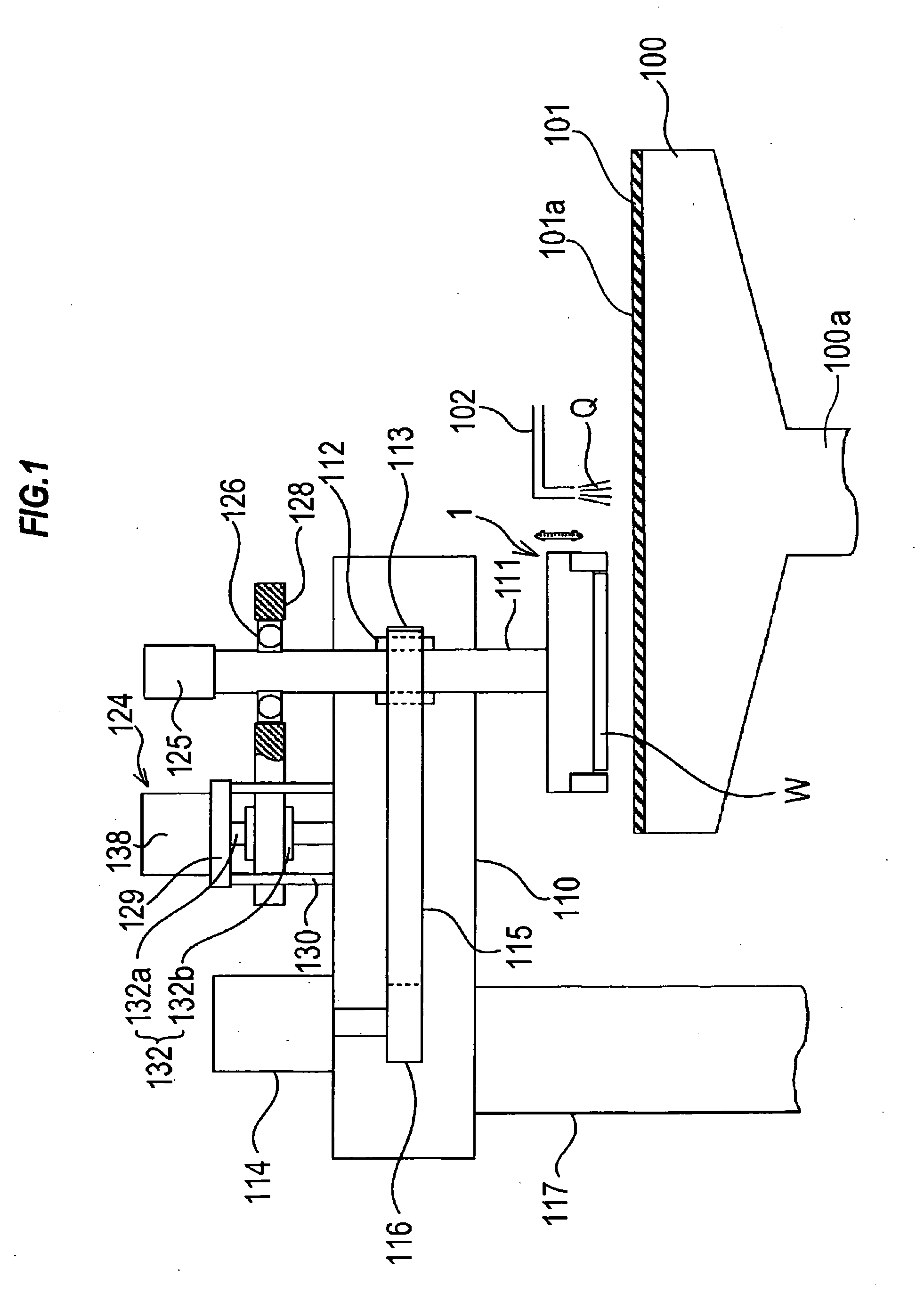
[0072]FIG. 1 is a schematic view showing an entire structure of a polishing apparatus according to an embodiment of the present invention. As shown in FIG. 1, the polishing apparatus comprises a polishing table 100, and a top ring 1 constituting a polishing head for holding a substrate such as a semiconductor wafer as an object to be polished and pressing the substrate against a polishing surface on the polishing table 100.

[0073]The polishing table 100 is coupled via a table shaft 100a to a motor (not shown) disposed below the polishing table 100. Thus, the polishing table 100 is rotatable about the table shaft 100a. A polishing pad 101 is attached to an upper surface of the polishing table 100. An ...


PUM

PropertyMeasurementUnit
diameteraaaaaaaaaa
timeaaaaaaaaaa
thicknessaaaaaaaaaa

Abstract

A polishing apparatus is used for polishing a substrate such as a semiconductor wafer to a flat mirror finish. The polishing apparatus includes a polishing table having a polishing surface, a polishing head having at least one elastic membrane configured to form a plurality of pressure chambers for being supplied with a pressurized fluid, and a controller configured to control supply of the pressurized fluid to the pressure chambers. The controller controls supply of the pressurized fluid so that the pressurized fluid is supplied first to the pressure chamber located at a central portion of the substrate when the substrate is brought into contact with the polishing surface, and then the pressurized fluid is supplied to the pressure chamber located at a radially outer side of the pressure chamber located at the central portion of the substrate.

Description

BACKGROUND OF THE INVENTION[0001]1. Field of the Invention[0002]The present invention relates to a polishing apparatus and method, and more particularly to a polishing apparatus and method for polishing an object to be polished (substrate) such as a semiconductor wafer to a flat mirror finish.[0003]2. Description of the Related Art[0004]In recent years, high integration and high density in semiconductor device demands smaller and smaller wiring patterns or interconnections and also more and more interconnection layers. Multilayer interconnections in smaller circuits result in greater steps which reflect surface irregularities on lower interconnection layers. An increase in the number of interconnection layers makes film coating performance (step coverage) poor over stepped configurations of thin films. Therefore, better multilayer interconnections need to have the improved step coverage and proper surface planarization. Further, since the depth of focus of a photolithographic optica...

Claims


Application Information

Patent Timeline
Patent Type & Authority Applications(United States)
IPC IPC(8): B24B1/00B24B7/10B24B37/30H01L21/304
CPCB24B37/30H01L21/304
Inventor YASUDA, HOZUMIFUKUSHIMA, MAKOTOTOGAWA, TETSUJI
Owner EBARA CORP
Why Eureka
Try Eureka