Reverse sliding seal for expandable tubular connections

a tubular connection and reverse sliding technology, applied in the direction of hose connection, screw threaded joint, borehole/well accessories, etc., can solve the problems of increased material cost, increased drilling time, and increased problem of bore hole siz

Inactive Publication Date: 2010-09-21
WEATHERFORD TECH HLDG LLC
View PDF100 Cites 12 Cited by
  • Summary
  • Abstract
  • Description
  • Claims
  • Application Information

AI Technical Summary

Benefits of technology

[0009]An expandable threaded connection between segments of expandable tubulars that provides a high bearing pressure seal between the pin and box members is disclosed. The present invention is a unique expandable threaded connection in which expansion of the tubulars creates a high pressure seal between the pin and box members. The invention utilizes a “groove” in a surface of the box member and a corresponding “rib” on the pin nose. The radial expansion of the tubulars via an expansion cone or via hydraulic pressure causes the pin to become shorter in length, thereby causing the pin nose to retract from the back of the box member. As the pin nose retracts, the rib on the pin nose moves backward until a portion of the rib contacts a portion of the groove in the box member. The point of contact between the rib and the groove creates a metal-to-metal seal between the pin and box members. Because the point of contact between the rib and the groove is a relatively small area, the force acting on the point of contact generates a high bearing pressure that is equal to or greater than the internal pressure within the expandable tubulars and, thus, generates a high pressure seal. Additionally, the contact between the rib and the groove may help to prevent further retracting of the pin nose from the back of the box.
[0012]In an alternative embodiment of the invention, an expandable elastomeric sealing ring can be inserted in a groove in the back of the box member such that when certain fluids contact the sealing ring as the pin nose retracts from the back of the box member, the sealing ring expands to fill the gap formed by the pin retracting from the box member thereby forming a secondary resilient seal that aids in containing the internal pressure until the primary metal-to-metal seal is completely formed.

Problems solved by technology

The large initial bore hole size requires increased drilling time and increased material costs, including increased use of materials such as drilling mud and casing cement.
Problems have arisen, however, at the threaded connection point between tubular segments during and after expansion when using conventional threaded tubular connections and seals currently available in the industry.
The radial expansion of a conventional threaded connection can cause the pin and box members to radially separate, thereby causing the seal of the threaded engagement to fail.
In effect, the radial expansion disables the seal that is created by the metal-to-metal engagement of the sealing surfaces of the pin and box members, and degrades or lowers the pressure holding integrity of the connections.
The threaded connection point thus becomes a source of potential leaks during and after expansion of the tubular string.
Conventional threaded connections that use an elastomeric seal ring between the engaged surfaces of the pin and box members may also leak when the threaded connection is radially expanded.
Radial expansion of the threaded connection, however, changes the radial compression of the elastomeric seal ring, thereby potentially allowing leakage through the threaded connection.
The resulting gap formed between the pin nose and the back of the box as a result of the axial movement of the pin nose creates a potential source of leakage through the threaded connection during and after the expansion process.

Method used


Image

  • Reverse sliding seal for expandable tubular connections
  • Reverse sliding seal for expandable tubular connections
  • Reverse sliding seal for expandable tubular connections

Examples


Embodiment Construction

[0022]The following examples are included to demonstrate preferred embodiments of the invention. It should be appreciated by those of skill in the art that the techniques disclosed in the examples which follow represent techniques discovered by the inventors to function well in the practice of the invention, and thus can be considered to constitute preferred modes for its practice. However, those of skill in the art should, in light of the present disclosure, appreciate that many changes can be made in the specific embodiments which are disclosed and still obtain a like or similar result without departing from the spirit and scope of the invention.

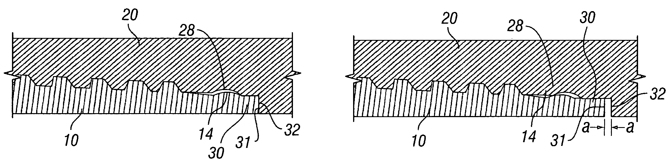
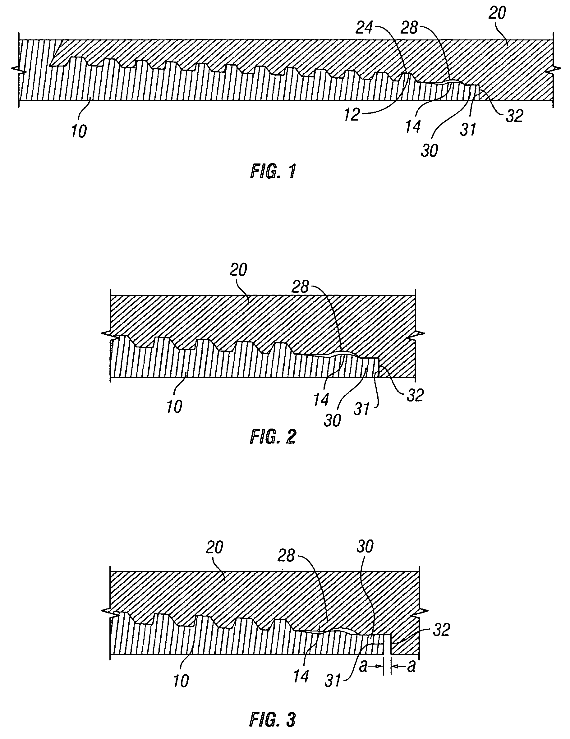
[0023]Referring to FIG. 1, an expandable threaded connection according to the present invention is shown fully made up. The expandable threaded connection of FIG. 1 includes pin member 10 and box member 20 on adjacent segments of expandable tubulars. Pin member 10 includes helical threads 12 extending along its length. Box member 20 includ...


PUM


Abstract

An expandable threaded connection between segments of expandable tubulars that provides a high bearing pressure seal at a specific area along the pin and box members is disclosed. The invention utilizes a “groove” in a surface of the box member and a corresponding “rib” on the pin nose. The radial expansion of the tubulars causes the pin to become shorter in length, thereby causing the pin nose to retract from the back of the box member. As the pin nose retracts, the rib on the pin nose moves backward until a portion of the rib contacts a portion of the groove in the box member. The point of contact between the rib and the groove creates a metal-to-metal seal between the pin and box members. Because the point of contact between the rib and the groove is a relatively small area, the force acting on the point of contact generates a high bearing pressure that is equal to or greater than the internal pressure within the expandable tubulars and, thus, generates a high pressure seal.

Description

FIELD OF THE INVENTION[0001]The present invention relates to threaded tubular connections particularly useful in the oil and gas industry. In particular, the invention relates to an expandable tubular threaded connection having a high bearing pressure metal-to-metal seal formed as a result of the tubular expansion process that allows the threaded connection to withstand high pressure after expansion.BACKGROUND OF THE INVENTION[0002]In the conventional drilling of an oil and gas well, a series of tubulars, typically strings of casing, liner, and / or screen segments connected together, are sequentially installed in the well bore until the depth of the producing zone of the formation is reached. Standard practice requires that each succeeding string of tubulars placed in the well bore has an outside diameter smaller than the preceding string of tubulars and / or bore hole such that the tubular segments can be passed through the preceding string of tubulars and / or bore hole to their downho...

Claims


Application Information

Patent Timeline
Patent Type & Authority Patents(United States)
IPC IPC(8): F16L13/14
CPCF16L15/003E21B43/106E21B17/08E21B43/103F16L15/04F16L15/02
Inventor HASHEM, GHAZI J.HARRALL, SIMON J.RING, LEV M.EVANS, MERLE E.
Owner WEATHERFORD TECH HLDG LLC
Why Eureka
Try Eureka