Compression connector for stranded wire

a compression connector and stranded wire technology, applied in the direction of contact members penetrating/cutting insulation/cable strands, electrical appliances, fastening/insulating connecting parts, etc., can solve the problems of insufficient initial crimp or radial force applied to hold the wire, inability to continue, and loose caps for the assembly that can be easily lost, so as to facilitate compression and prevent retraction

Active Publication Date: 2009-03-10
HOLLAND ELECTRONICS
View PDF12 Cites 51 Cited by
  • Summary
  • Abstract
  • Description
  • Claims
  • Application Information

AI Technical Summary

Benefits of technology

[0014]In operation of the preferred embodiment, the end of a cable having a stranded conductor is inserted into the trailing end of the axial bore of the compression sleeve and advanced therethrough and into the axial conduit of the connector body. As the cable is advanced into the axial cavity, the stranded conductor is separated and splayed in 360 degrees when forced against the apex of the conical centerpost. In the preferred embodiment, the leading end of the axial conduit is not curved. Accordingly, when the cable is fully advanced into the connector body by twisting and forward pressure on the wire, the leading ends of the splayed stranded conductor are not recurved as with the first embodiment. A further advantage of the preferred embodiment is that an installer can be relatively certain that the wire is fully advanced into the axial cavity and that the leading end of the wire abuts the base of the threaded shaft because further twisting and pressure do not advance the wire into the cavity. The compression sleeve is then advanced over the trailing end of the connector body to force the connector body, which may be slotted to facilitate compression, radially inwardly, compressing the strands of wire between the threaded outer surface of the shaft and the inner surface of the axial conduit in the connector body. Due to the thread on the outer surface of the shaft, the compression is operable for securely holding the entrapped and compressed strands of wire between the wall of the axial conduit and the centerpost. When the compression sleeve is fully advanced over the connector body, an optional detent on the inner surface of the axial bore of the compression sleeve engages a mating detent on the outer surface of the connector body and locks the compression sleeve in position to prevent retraction thereof. The surface of the axial cavity and the spiral thread on the outer surface of the centerpost between which the strands are entrapped prevent the wire from being pulled from the connector when tension is applied thereto.

Problems solved by technology

The limitation in these designs is that a stranded wire conductor has spaces between strands, even after compression.
The strands of the wire will move to fill the void resulting in the initial crimp or radial force originally applied to hold the wire being inadequate to continue to securely hold the wire.
A problem with this fitting is that it requires a separate loose cap for the assembly that can be easily lost.
A further disadvantage in this type of fitting is that if the strands of wire comprising the conductor undergo corrosion, tension on the wire may cause the stripped portion to pull out of the adapter and, accordingly, the fitting.
A limitation and disadvantage of the connector of Korte et al. is that the prong is funnel-shaped and when lateral pressure is exerted on the cable jacket during the compression step, the lateral forces (directed radially inwardly) tend to force the stranded wire rearwardly (i.e., off of the prong) due to the conical shape of the prong, and rearward tension on the cable may separate the cable from the connector.
The limitations of this design further include the need to assure the wire is pushed forward sufficiently onto the sloped prong to result in the required holding force, the stranded wire slipping rearwardly off of the smooth surface of the prong as the connector is being handled and compressed, and that the strands remain in the same plane as the pulling force.
In addition, the insertion of the rear plug must be complete to effect the designed holding and whose forward motion could be limited by the stranded wire not aligning directly onto the prong and sitting on one side.
This would not allow the plug to be fully inserted.

Method used


Image

  • Compression connector for stranded wire
  • Compression connector for stranded wire
  • Compression connector for stranded wire

Examples


Embodiment Construction

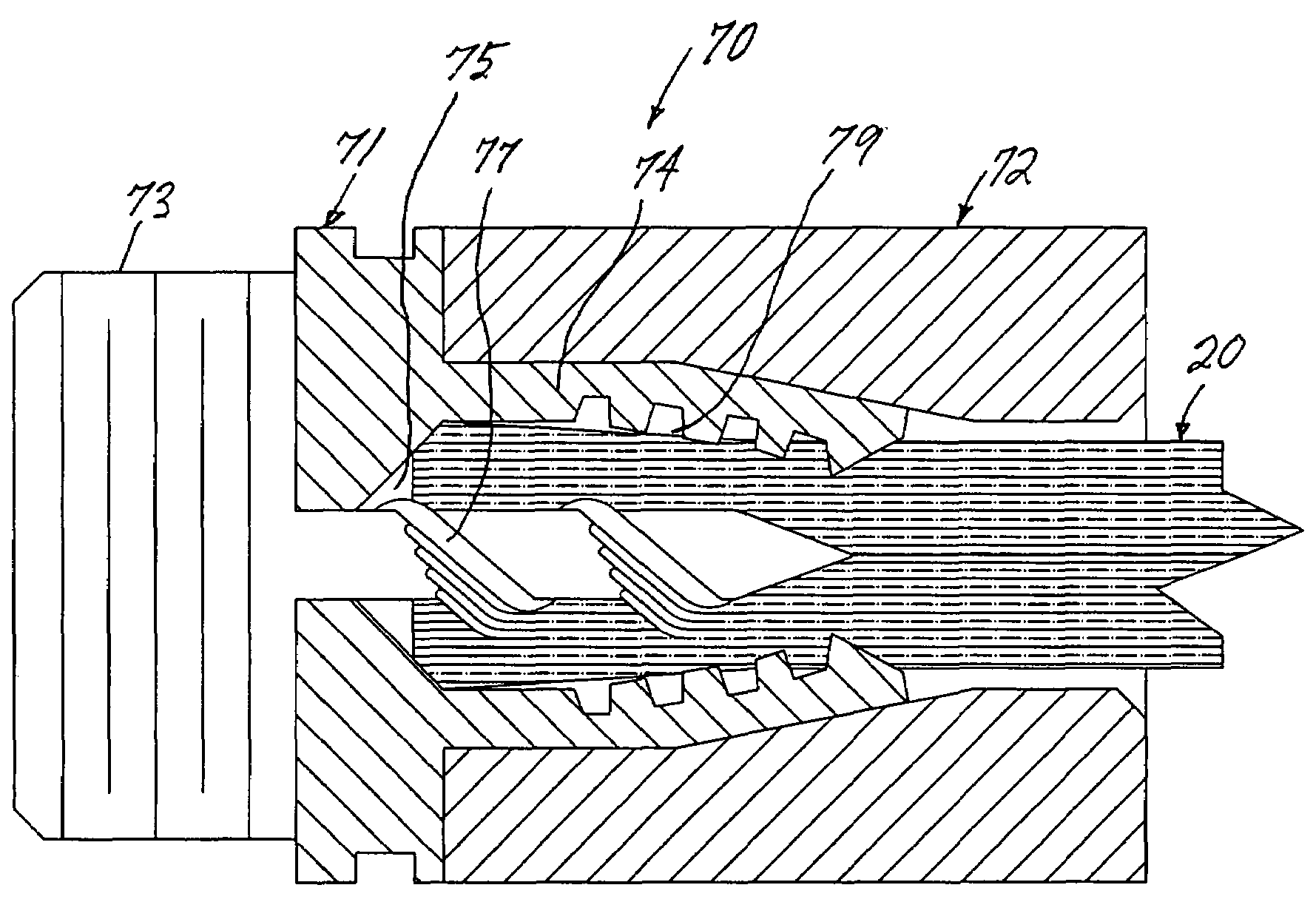
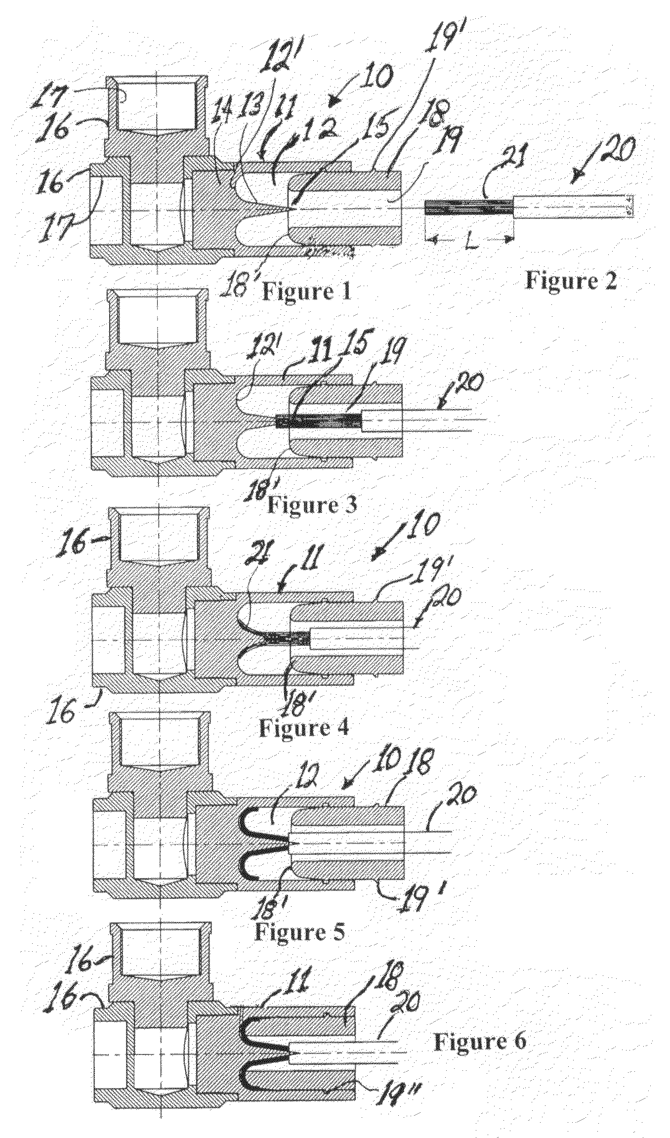
[0034]FIG. 1 is a compression-type connector 10 operable for attachment to a wire having a stranded central conductor in accordance with a first embodiment of the present invention. The connector 10 is illustrated in cross-sectional side view in an open position prior to attachment to a wire. The connector 10 includes a tubular connector body 11 having an axial cavity 12 therewithin. The leading end 12′ of the axial cavity 12 is contoured and has the form of the surface of a hemitorus. A conical centerpost 13 is disposed within the axial cavity 12 at the leading end thereof. The base 14 of the conical centerpost 13 is circular and centered within the leading end 12′ of axial cavity 12. The apex 15 of the conical centerpost is axially disposed to be colinear with the axis of the axial cavity. The leading end of the connector body 11 is attached to at least one, and more preferably two, as shown in the figures, connector terminal adapter 16 having a threaded interior surface 17. The c...


PUM


Abstract

Compression-type connectors for attaching wires ranging in size from #10-16 and having stranded conductors. The connector is similar to coaxial cable connectors in that it includes a connector terminal adapter, a connector body attached to the connector terminal adapter, the connector body having an axial cavity dimensioned to receive a wire in a trailing end thereof, a centerpost disposed within the axial cavity that has a conical tip projecting rearwardly, and a compression sleeve slidably mounted either within the trailing end of the cavity or overlying the trailing end of the connector body. In one embodiment the centerpost is conical with the base of the cone disposed at the leading end of the cavity and the apex of the cone projecting rearwardly and a threaded outer surface therebetween. In a preferred embodiment, the centerpost has a straight threaded shaft with a conical tip. The connector terminal adapter is operable for attachment to a variety of conductive terminals.

Description

CROSS REFERENCE TO RELATED APPLICATIONS[0001]This application is a continuation-in-part of Nonprovisional Application U.S. Ser. No. 11 / 591,690, filed Nov. 1, 2006 now U.S. Pat. No. 7,364,462, which claims the benefit of U.S. Provisional Application Ser. Nos. 60 / 797,323, filed May 2, 2006, and 60 / 854,321, filed Oct. 24, 2006.BACKGROUND OF THE INVENTION[0002]1. Field of the Invention[0003]The present invention relates to a compression connector for use with electrically conductive wires having a stranded center conductor.[0004]2. Prior Art[0005]A variety of methods are currently employed for attaching the stranded center conductor of a wire to a terminal. Most methods require that a portion of the jacket covering of the wire be stripped to expose a portion of the stranded conductor. The stripped portion of the wire is then inserted into the hollow sleeve of a connector such as a spade lug and radial pressure is applied to the sleeve with a crimping tool to prevent longitudinal force f...

Claims


Application Information

Patent Timeline
Patent Type & Authority Patents(United States)
IPC IPC(8): H01R11/20
CPCH01R4/2412H01R4/5033
Inventor HOLLAND, MICHAELMCCULLEY, MICHAEL
Owner HOLLAND ELECTRONICS
Why Eureka
Try Eureka